Bicycle Shredder V2
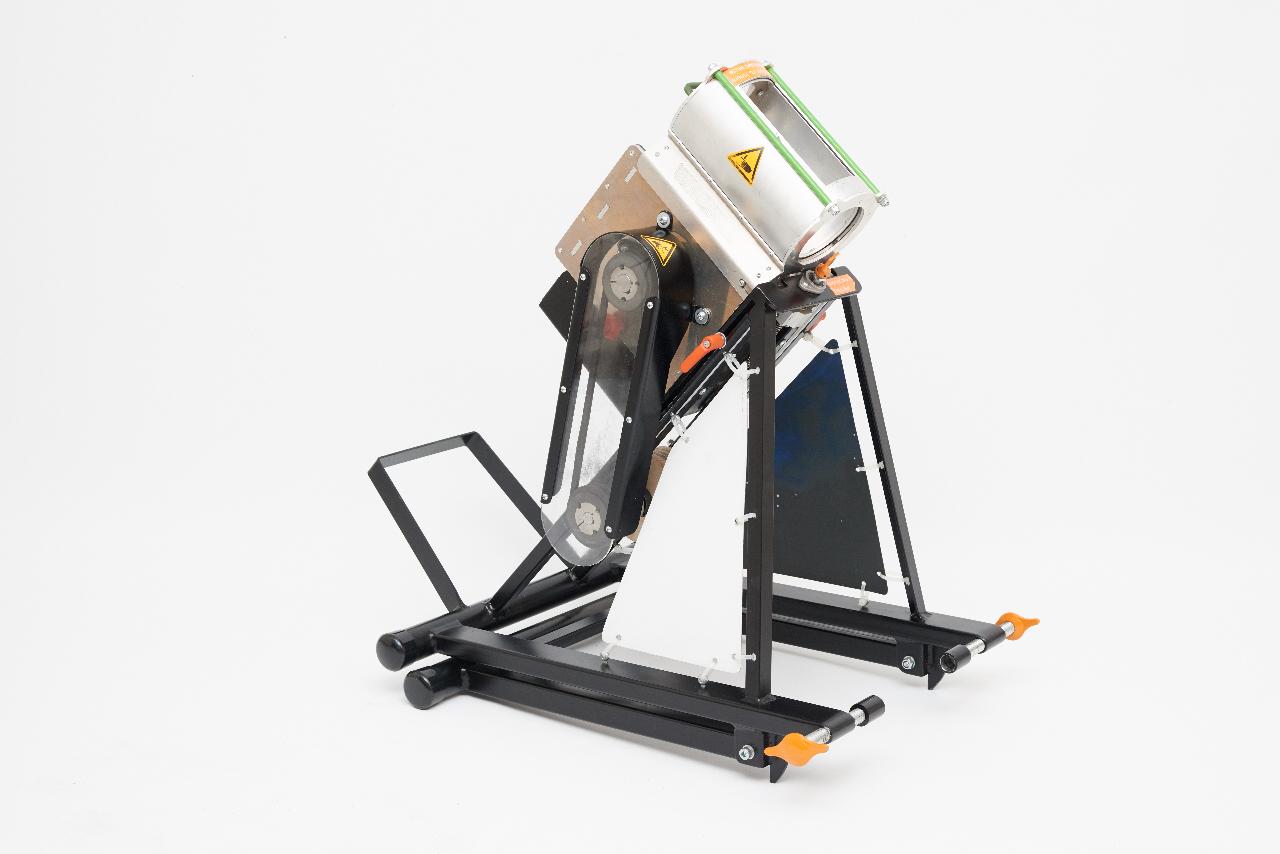
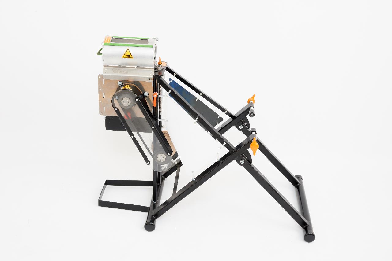
In this how-to we’re giving you an overview about the construction of our bicycle shredder. One and a half years ago we made the first video about how to build a bicycle shredder. Since then, we made further adjustments and are now proud to present you the second version of the machine (with a much better documentation).
—
Attachments
Resources
3D Files
Step 1 - Get ready!
In the download package you find a lot of files and drawings. At first sight it might be overwhelming, but don’t be afraid, we’re taking care of you ;-).
In addition to the download-kit, the following steps will give you further information, why the shredder is built the way it is. Furthermore a short introduction video and an assembling video is in the making to get a better understanding about the construction. Stay tuned!
Download-Link: https://www.dropbox.com/sh/xlts122wcb905q6/AABRgMZTki8gH1NqQ5SvOS-Ia?dl=0
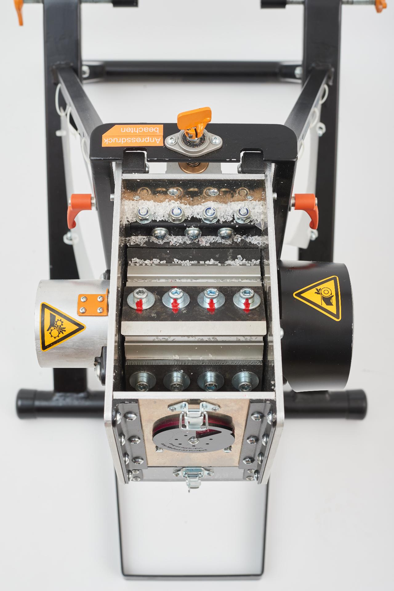
Step 2 - Cutting Mill
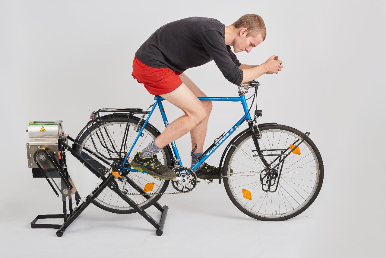
Nearly all low speed shredders we saw in the community or around the internet were huge, heavy or sometimes not even working proper and efficient. Using high speed instead, we have the power of inertia :-). So we decided to shred plastic with human power at high speed.
There are different ways to build the axle. We decided to spend a bit more money on standard parts to reduce costs as machining and post machining on the lathe. That’s why we use those span sockets. However, we are aware that these components are not available in every country in the world. Take a look on the possibilities and competencies around you, it is also possible to manufacture the axle in a different way.
There are different ways to build the axle. We decided to spend a bit more money on standard parts to reduce costs as machining and post machining on the lathe. That’s why we use those span sockets. However, we are aware that these components are not available in every country in the world. Take a look on the possibilities and competencies around you, it is also possible to manufacture the axle in a different way.
Step 3 - Material Lock
Shredding plastic with the bicycle shredder - the knives of the cutting mill should run at high speed. To ensure a safe and stable shredding process, we needed a way to get the plastic into the cutting mill without opening it. In the past we worked with several versions of a pipe lock. Finally, we dismissed the pipe lock because of malfunctions. That's why we developed a more classic and simple version of a save hopper. The downside of the new version is the huge size and weight compared to the old one.
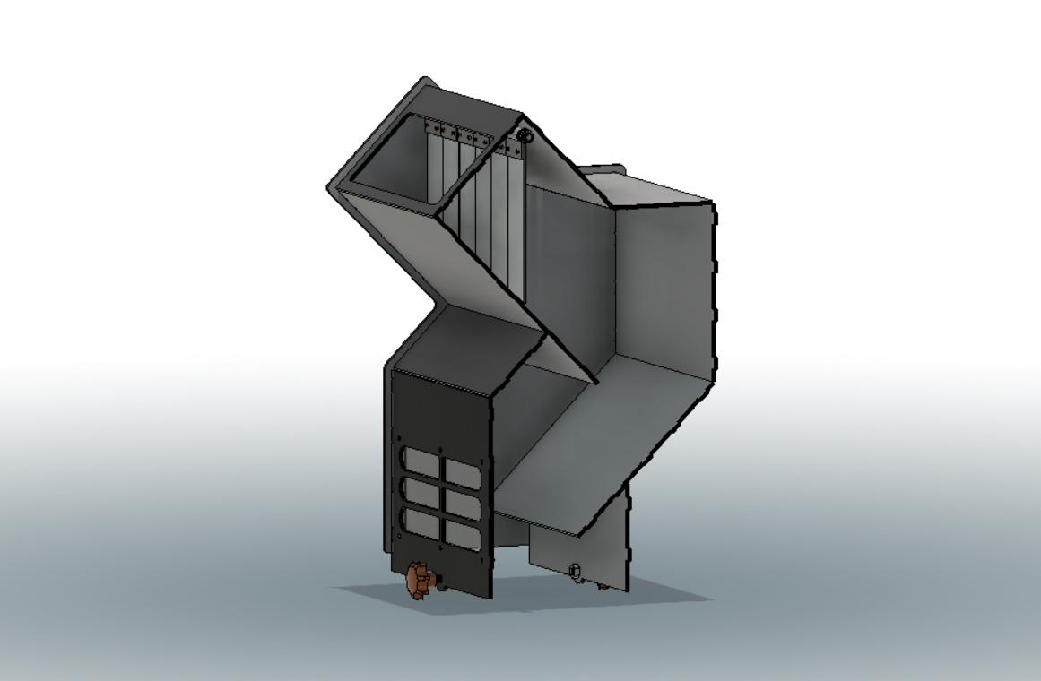
Step 4 - Sieve and Collection Box
The sieve and collection box is nothing really special, just bended and welded metal sheets. We recommend using a sieve with holes about 5 - 8 mm in diameter. Very small holes will turn the plastic nearly into dust. Don't go too thin with the thickness of the metal sheet. It is important for stability and the locking system! 1,5 mm are a good size.
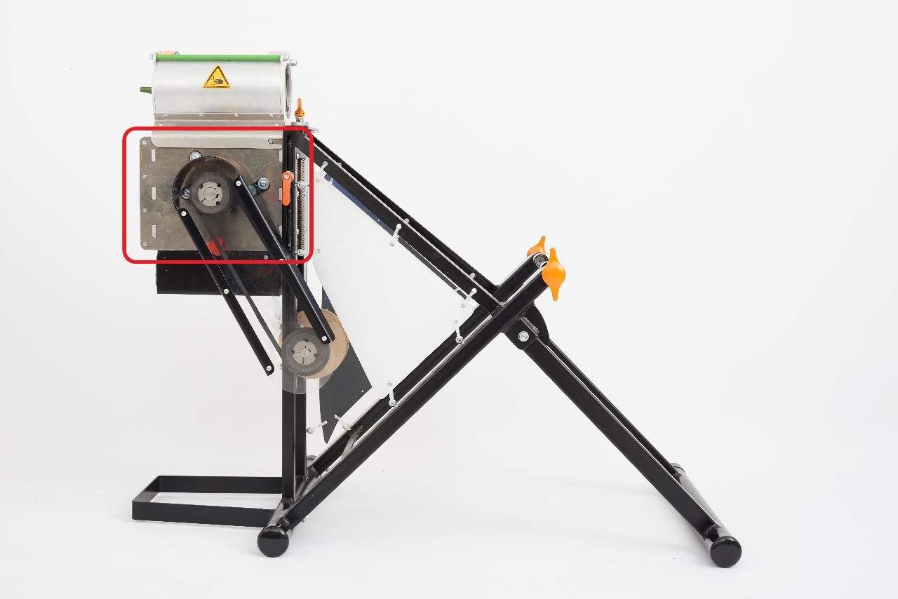
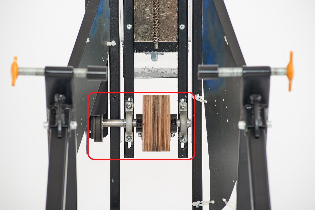
Step 5 - Friction Wheel
The friction wheel transfers the speed from the rear wheel to the cutting mill. We use plywood for the wheel because we can mill it with our own cnc machine. Nethertheless there are definitely better materials for the friction wheel, for example something out of plastic.
Step 6 - Steel Frame
Building the steel frame requires proper knowledge and experience in welding and working with metal. If you’re new in the game, look for someone with experience in metalwork.To simplify the welding process we prepared gauges -> plywood sheets to keep the right distances between the steel tubes and some big 45° angles.
Before welding everything make sure everything is drilled and milled into the steel tubes. Afterwards it's a bit tricky to get them to the right places!
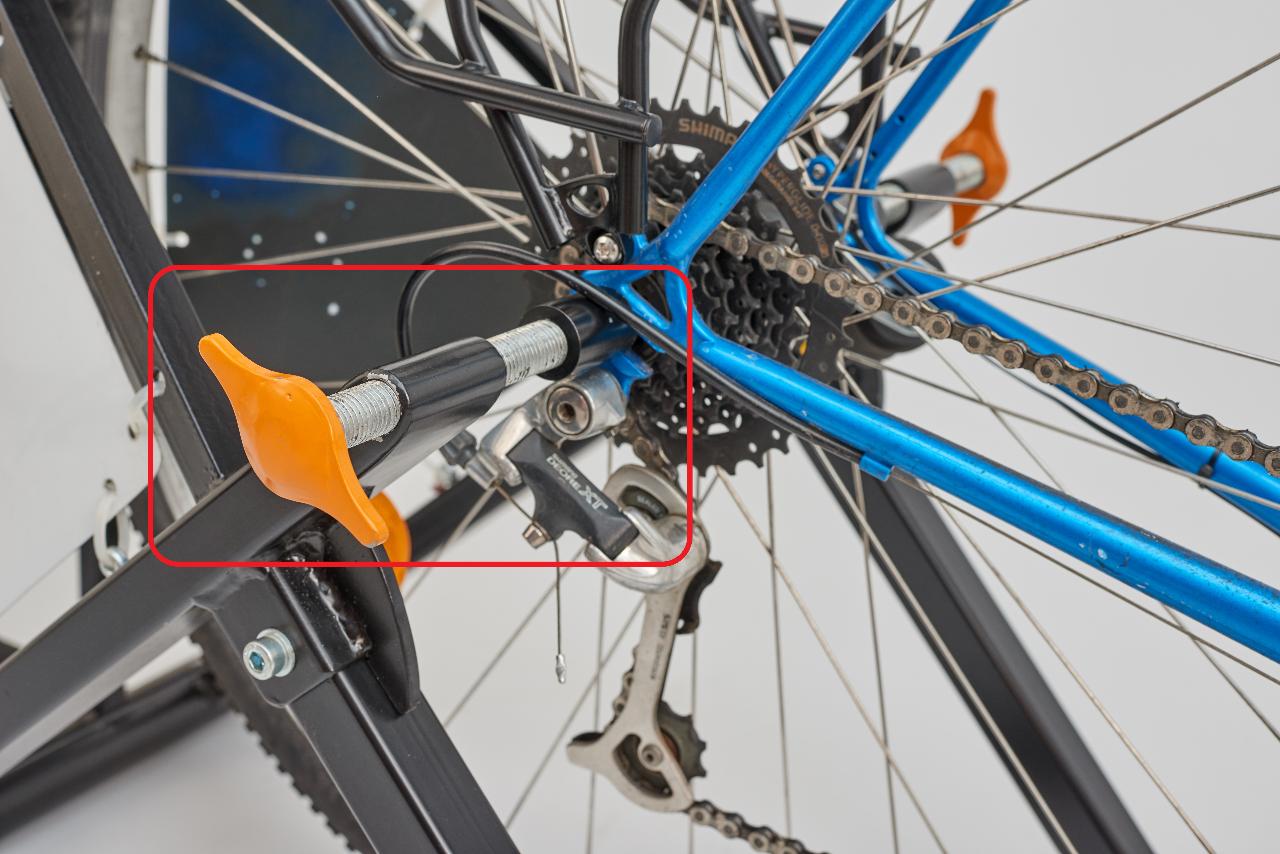
Another advice: welding the m16 nuts; make sure the two nuts are in one alignment. That's important to clamp the rear-wheel right in place. We take a long steel bar (14mm in diameter).
Before welding everything make sure everything is drilled and milled into the steel tubes. Afterwards it's a bit tricky to get them to the right places!
Another advice: welding the m16 nuts; make sure the two nuts are in one alignment. That's important to clamp the rear-wheel right in place. We take a long steel bar (14mm in diameter).
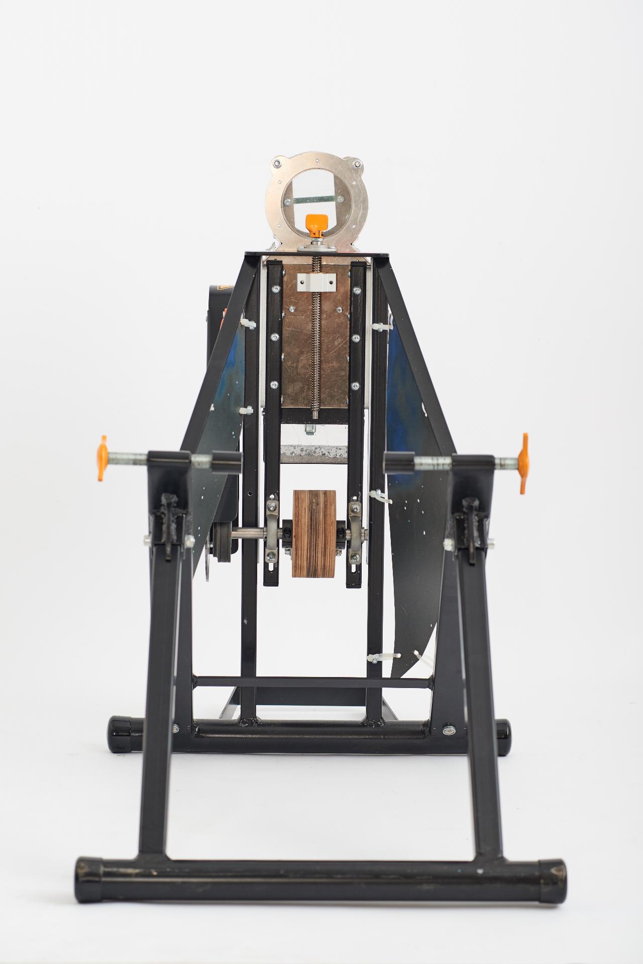
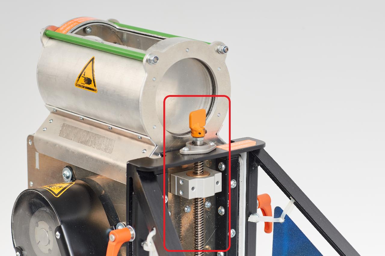
Step 7 - Height Adjustment
The height adjustment is one of the fastest things you can realise :-).
For the turning knob we welded a small steel strip on a clamping ring. The rest of it are just ready-to-use standard parts.
For the turning knob we welded a small steel strip on a clamping ring. The rest of it are just ready-to-use standard parts.
Step 8 - Wheel Mount
The wheel-mount is a lot of lathe work but not too complex!
For the turning knob we lasered a part out of a thick metal sheet and welded it on a nut. Instead of a lasered part you can realise the turning knob as well by some steel strips and an angle grinder.
For the turning knob we lasered a part out of a thick metal sheet and welded it on a nut. Instead of a lasered part you can realise the turning knob as well by some steel strips and an angle grinder.


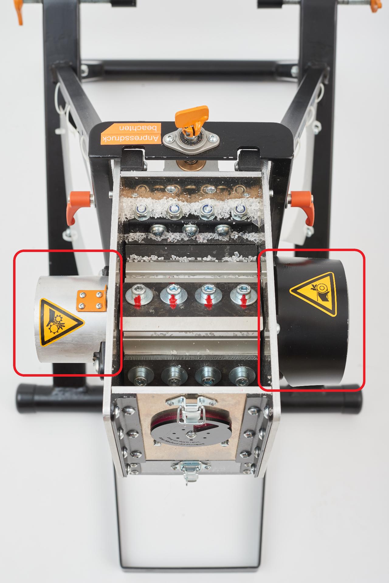
Step 9 - Safety Add-ons
Workshops with different kinds of people are our daily business. That is why we care a lot about safety!
To ensure an easy and understandable handling, a good way is to use our color system.
- Green: Everybody can touch/use it.
- Orange: The team can touch/use it.
- Red: Keep your body away from it, it's f***ing dangerous!
In addition to the color system we use common warning signs and tips and tricks written on the machine.
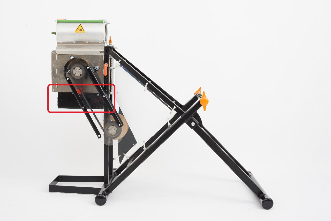
Furthermore we build safety add-ons, such as the belt protection and the shaft protection.
If you have ideas how to make the machine safer and better, feel free to share it with us and the community!
To ensure an easy and understandable handling, a good way is to use our color system.
- Green: Everybody can touch/use it.
- Orange: The team can touch/use it.
- Red: Keep your body away from it, it's f***ing dangerous!
In addition to the color system we use common warning signs and tips and tricks written on the machine.
Furthermore we build safety add-ons, such as the belt protection and the shaft protection.
If you have ideas how to make the machine safer and better, feel free to share it with us and the community!
—
—
—
Comments