Make a mould to bend sheets
Bending plastic sheets is a relatively easy technique, at least compared to metal and wood. Once you have a mould you can use it over and over again to get the exact same shape. This specific how-to aims to build a simple mould from plywood and sheet metal for bending sheets in one direction. Steps 1-4 guide you through the design and preparation process, while steps 5-14 explain how to build the actual mould.
—
Attachments
Resources
3D Files
- 3D Step File: /files/example_mould/example_mould.stp - Preview
Step 1 - Prototyping
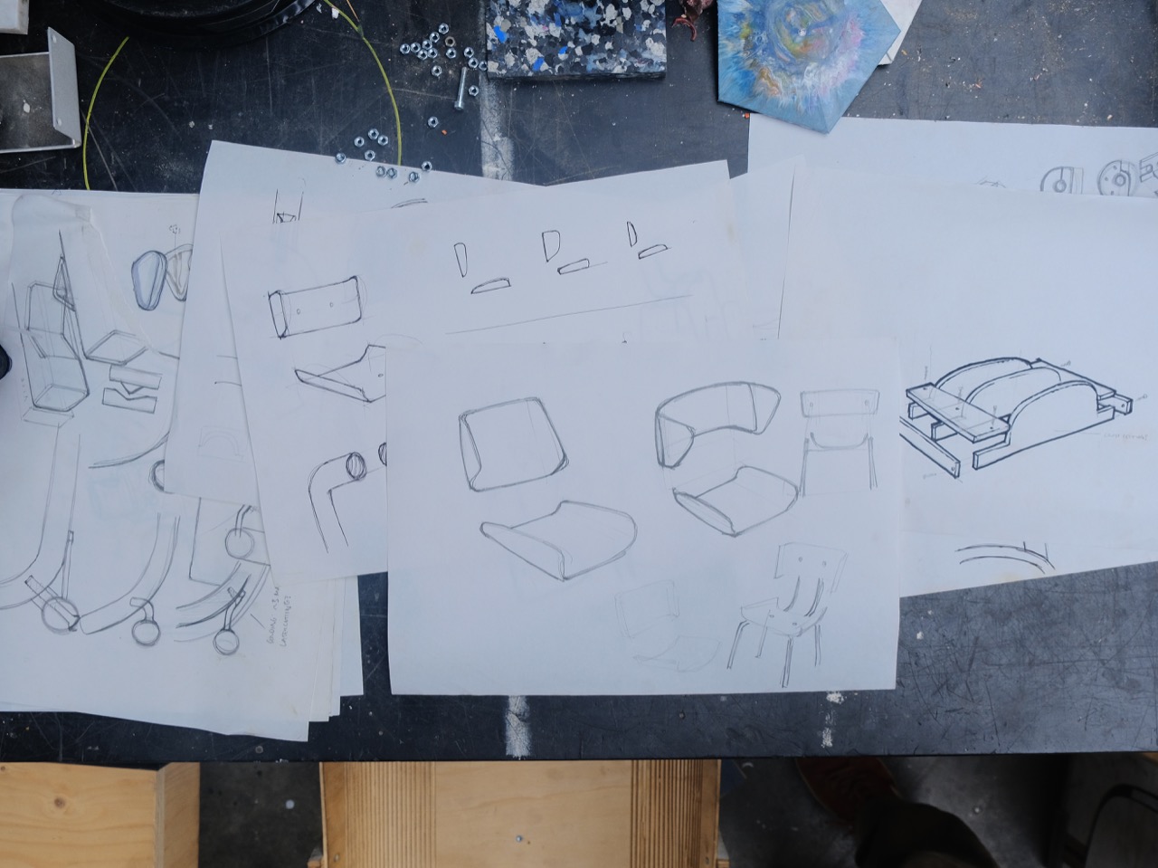
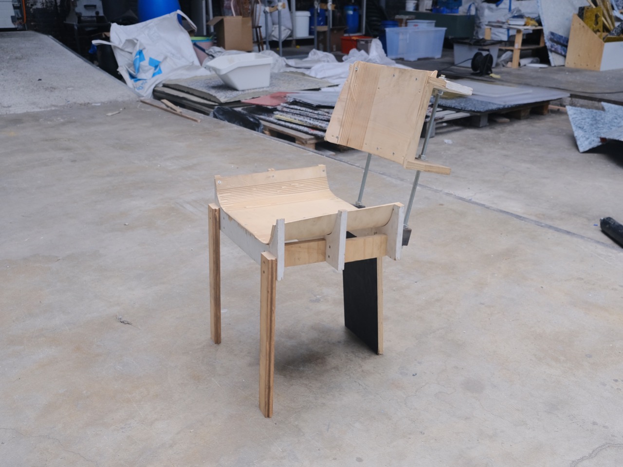
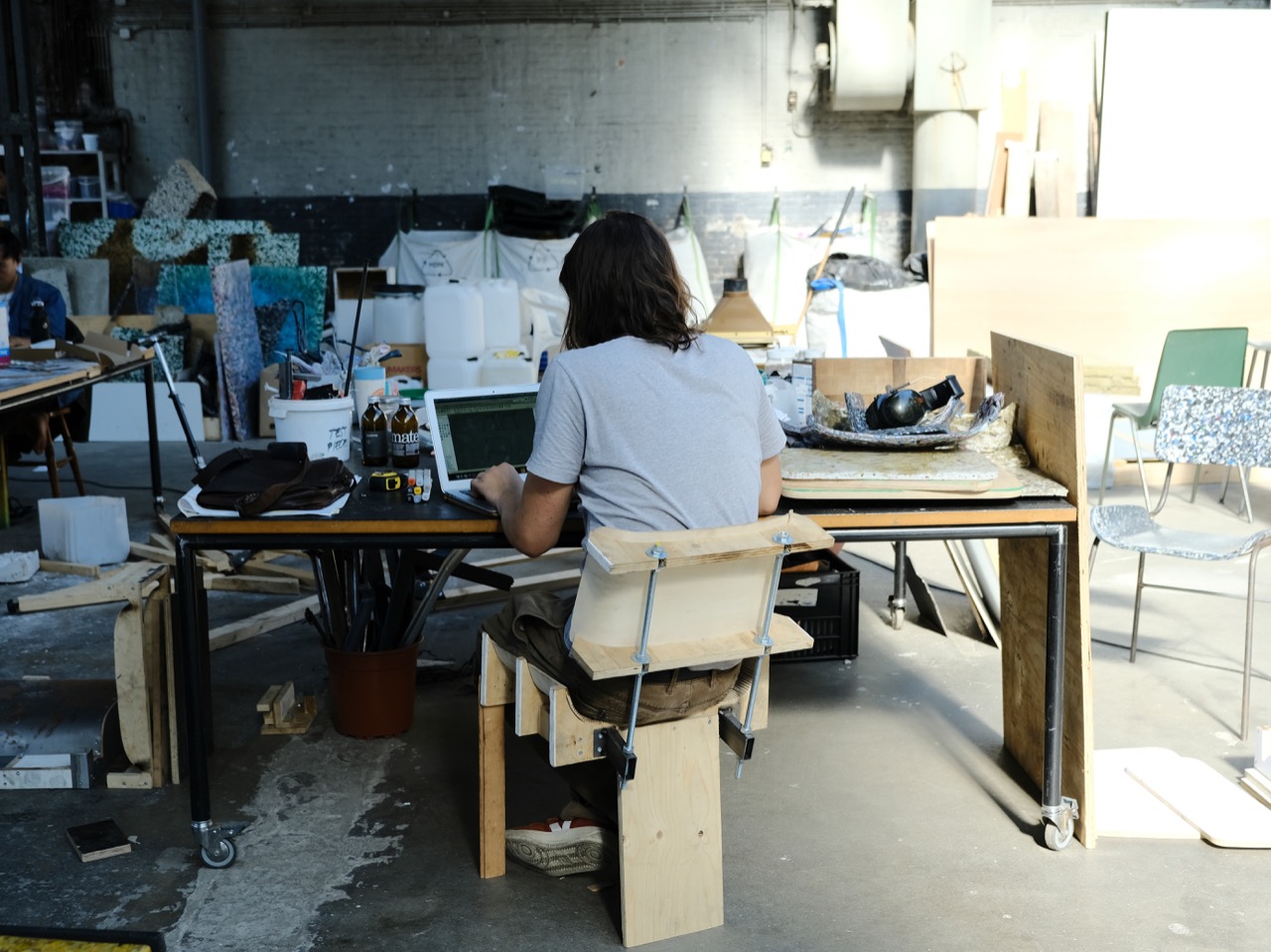
It’s kind of obvious, but first things first: before making a proper mould, you should figure out what exactly you want to achieve. It’s easy to build a rough prototype from plywood or cardboard to test proportions and ergonomics. So right after sketching out your design, go and test it.
Step 2 - 3D modelling
Take all the measurements you derived from your prototype and feed it to CAD. For curvatures, take a quick photo, place it in CAD, scale it to the right size and rebuild the curve from there.
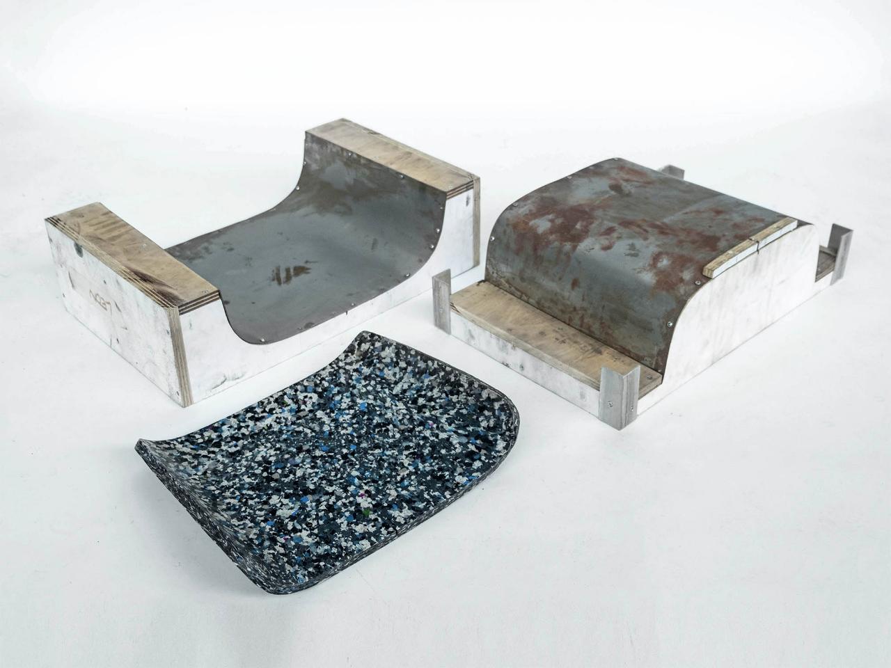
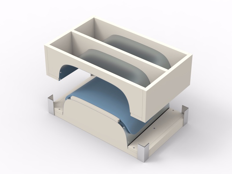
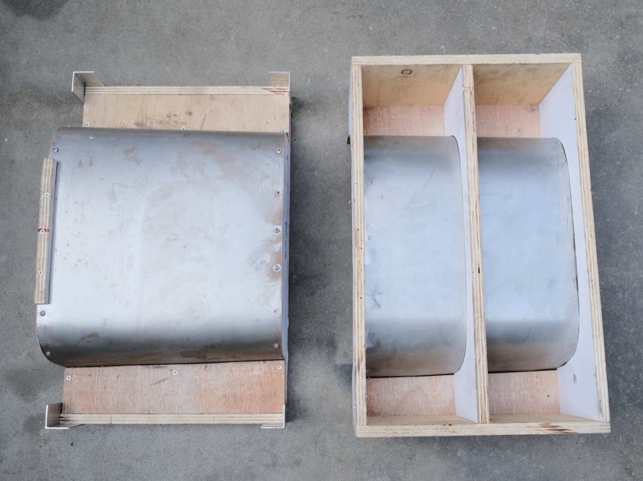
The mould consists of two parts, the positive and the negative half that encapsulate your desired part from both sides. The bending surface is a 1mm sheet metal screwed onto cross-sections cut from plywood. The surface offset of both halves should be set to the material thickness of your plastic sheets.
See the attached .step file for an example mould.
Step 3 - Making the drawings: 3D to vector
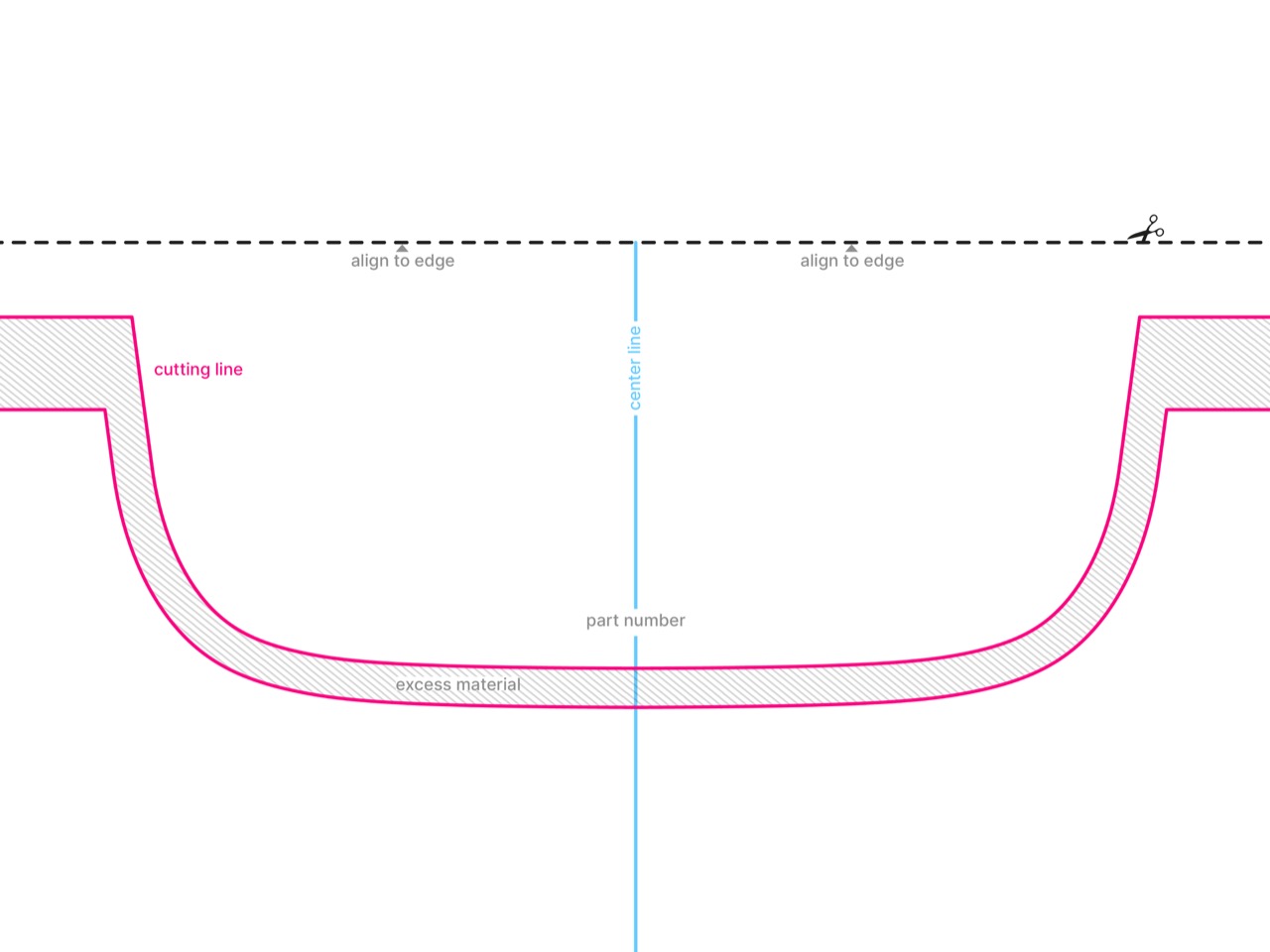
The aim of the drawing is to transfer the precise measurements and curvatures from your CAD model to a physical mould. A good way to do that is to make 2D drawings, print them, laminate them onto plywood and cut them with a bandsaw or jigsaw. While you’re making the drawings for each part, try to anticipate how you are going to use those drawings. A smart way of avoiding a large format print is to figure out how to put together several standard sized prints. Anyways, you cannot rely on the printer to align your print perfectly on the page, so add an alignment line on every drawing.
Step 4 - Making the drawings: layout
Besides that, every sheet should contain some sort of part number or description, not to mix them up later. When moving from one application to another or while printing, pay extra attention to always maintain the same scale!
Use dashed or colored lines for different purposes (e.g. cutting, aligning, centerline …) and hatched areas for offcuts. The lines you print should be as thin as possible and use pure CMYK tones (e.g. 0 0 0 100 for black). This will avoid imprecise lines due a potential registration misalignment in the printer.
Use dashed or colored lines for different purposes (e.g. cutting, aligning, centerline …) and hatched areas for offcuts. The lines you print should be as thin as possible and use pure CMYK tones (e.g. 0 0 0 100 for black). This will avoid imprecise lines due a potential registration misalignment in the printer.

Step 5 - Preparing the material
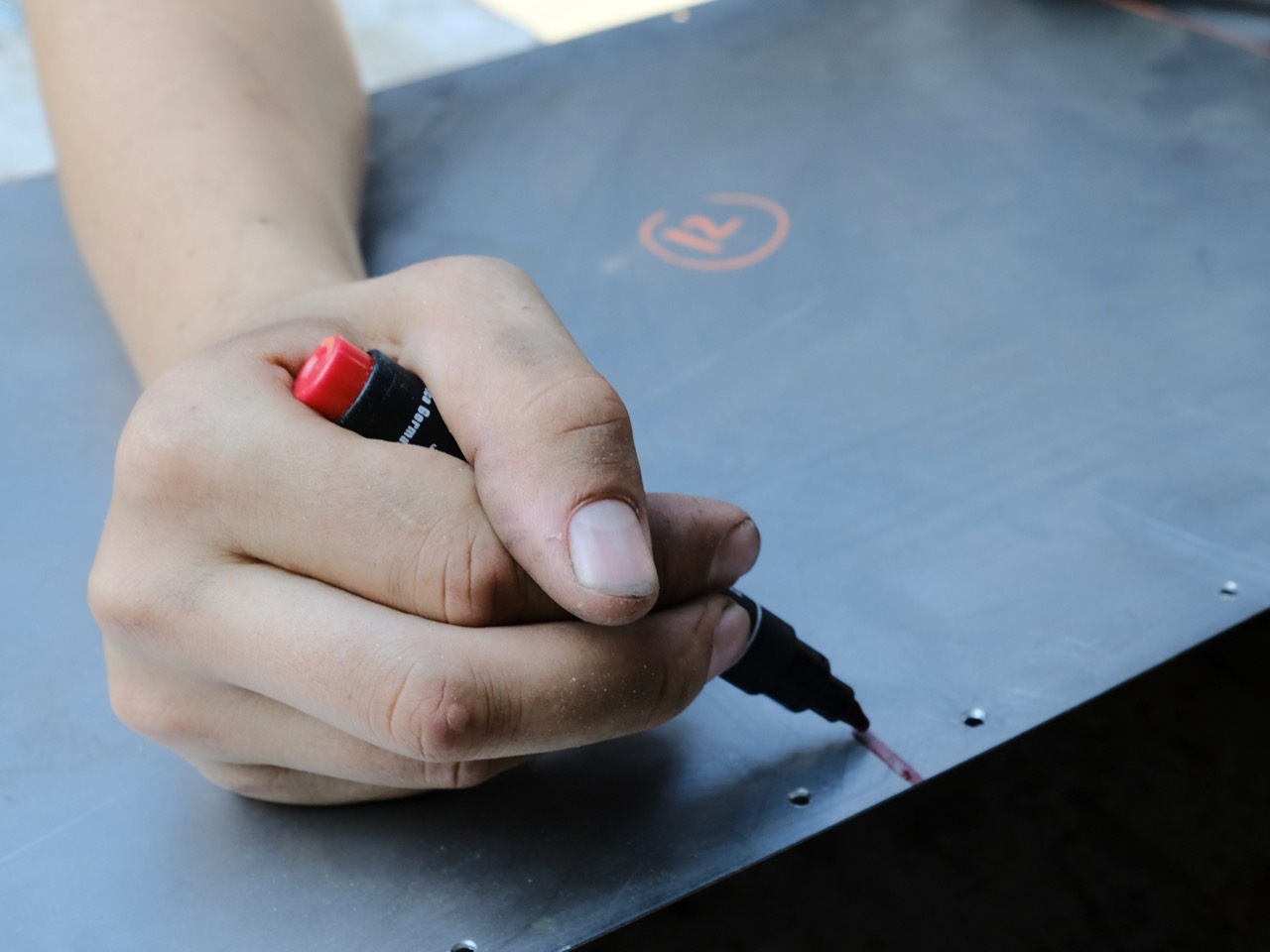
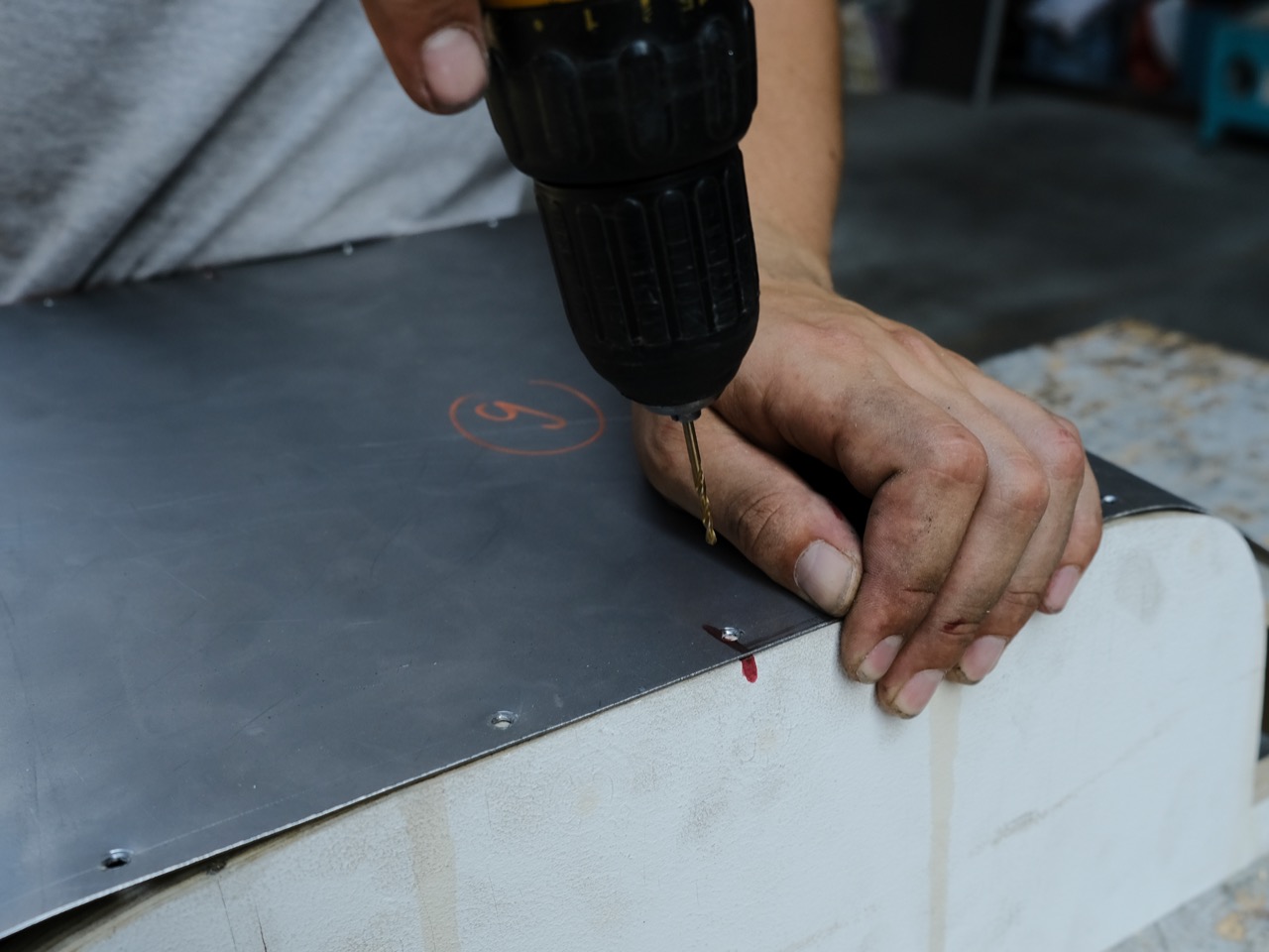
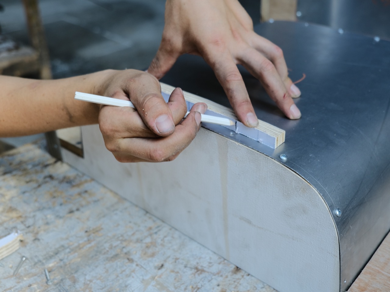
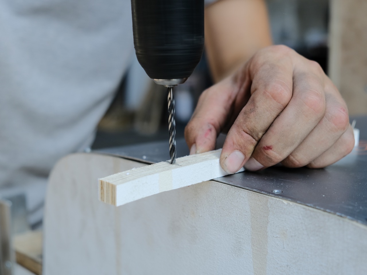
Get all the dimensions from your CAD model and cut all parts at the same time to speed up the process. Drill holes parallel to the long edge of the sheet metal with half the cross-sections material thickness as an offset.
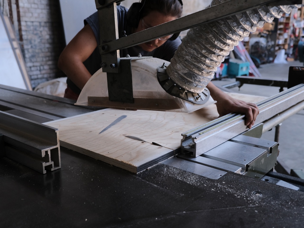

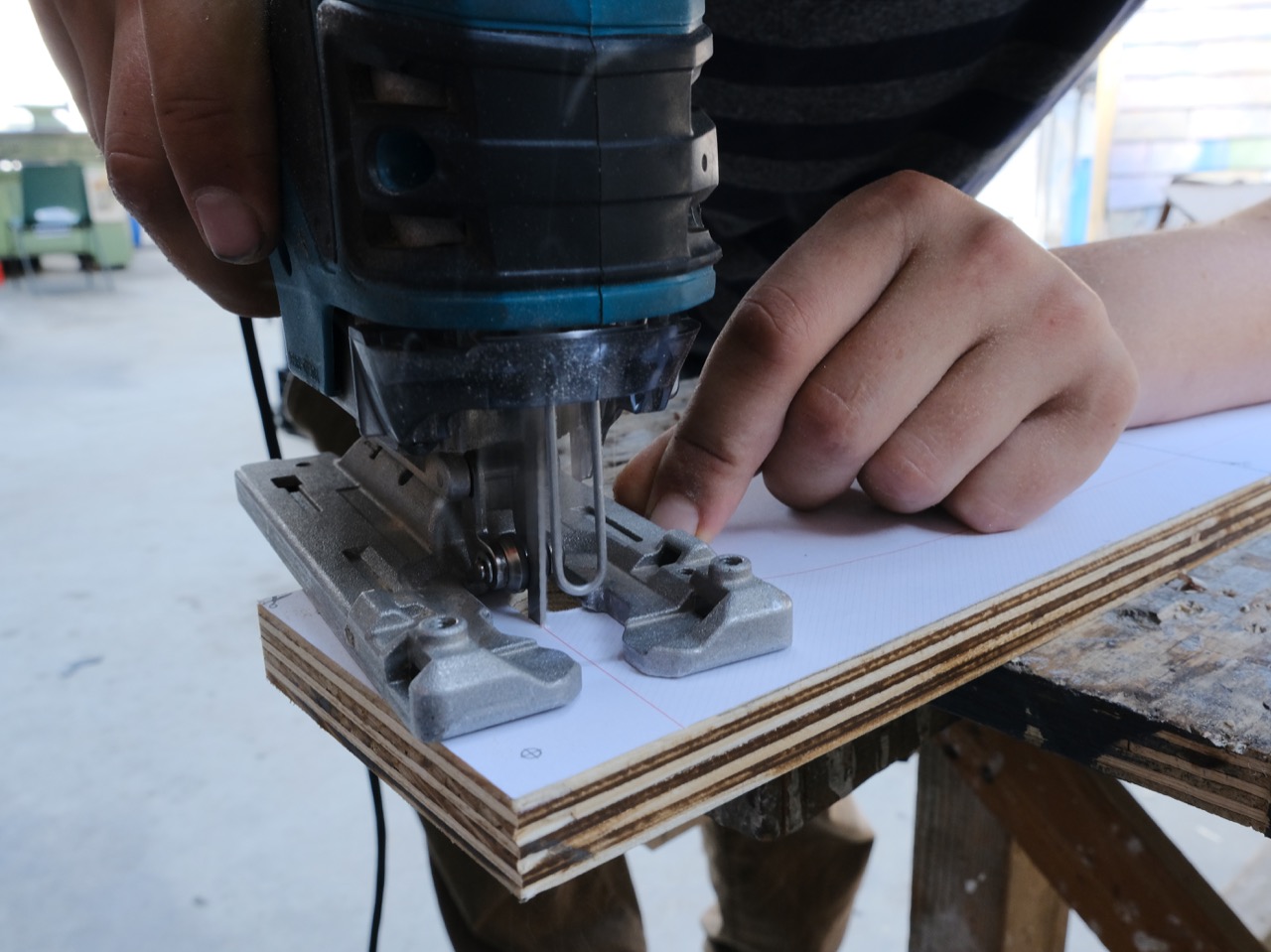
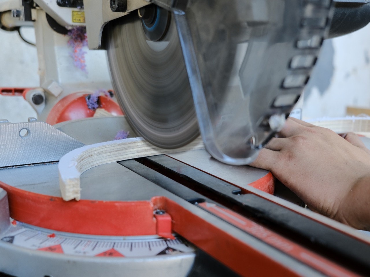
Step 6 - Cutting the cross-sections
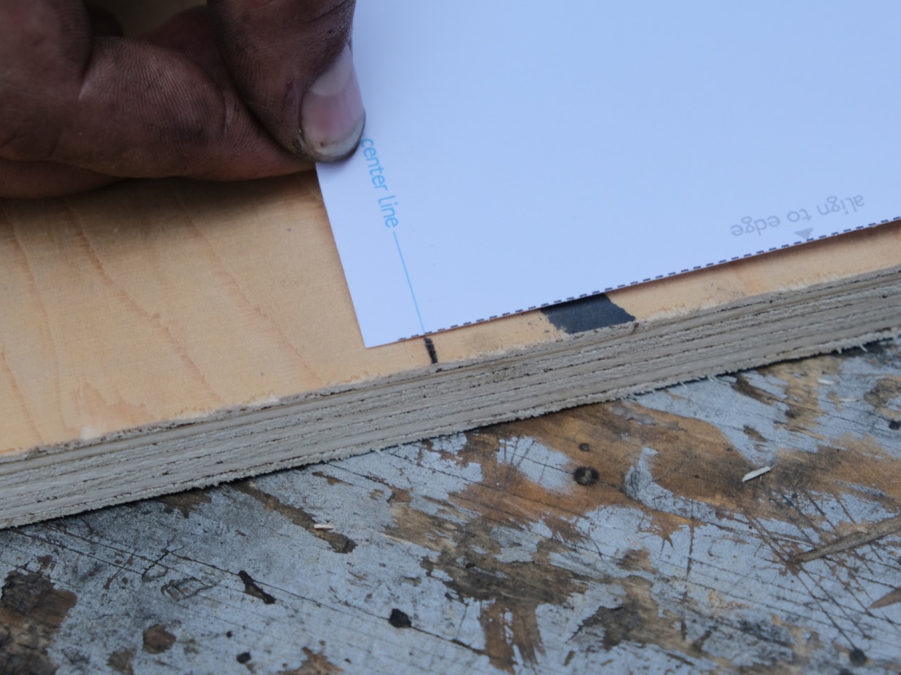
Cut the drawings as you planned before. Use a ruler and a sharp knife and work precisely. Then take the previously cut plywood parts and laminate them with the drawings. If there are several drawings for one part, starting from the center. Apply spray mount on the back of one sheet, align it according to the instructions and sweep from the middle outwards.
Drill holes for the jigsaw to dive in and cut along the lines. Keep in mind what you want to keep and what’s going to be off-cut. Smoothen the edges with sandpaper.
Drill holes for the jigsaw to dive in and cut along the lines. Keep in mind what you want to keep and what’s going to be off-cut. Smoothen the edges with sandpaper.

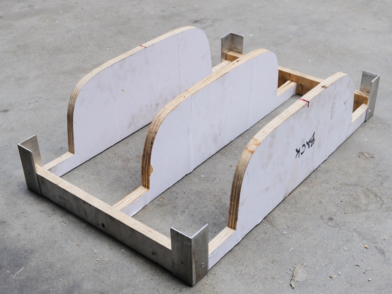
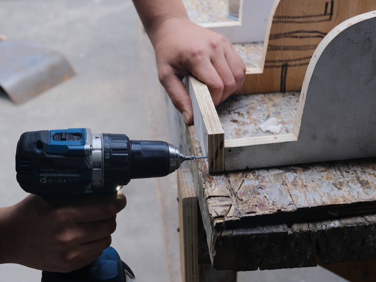
Step 7 - Assembling the frames
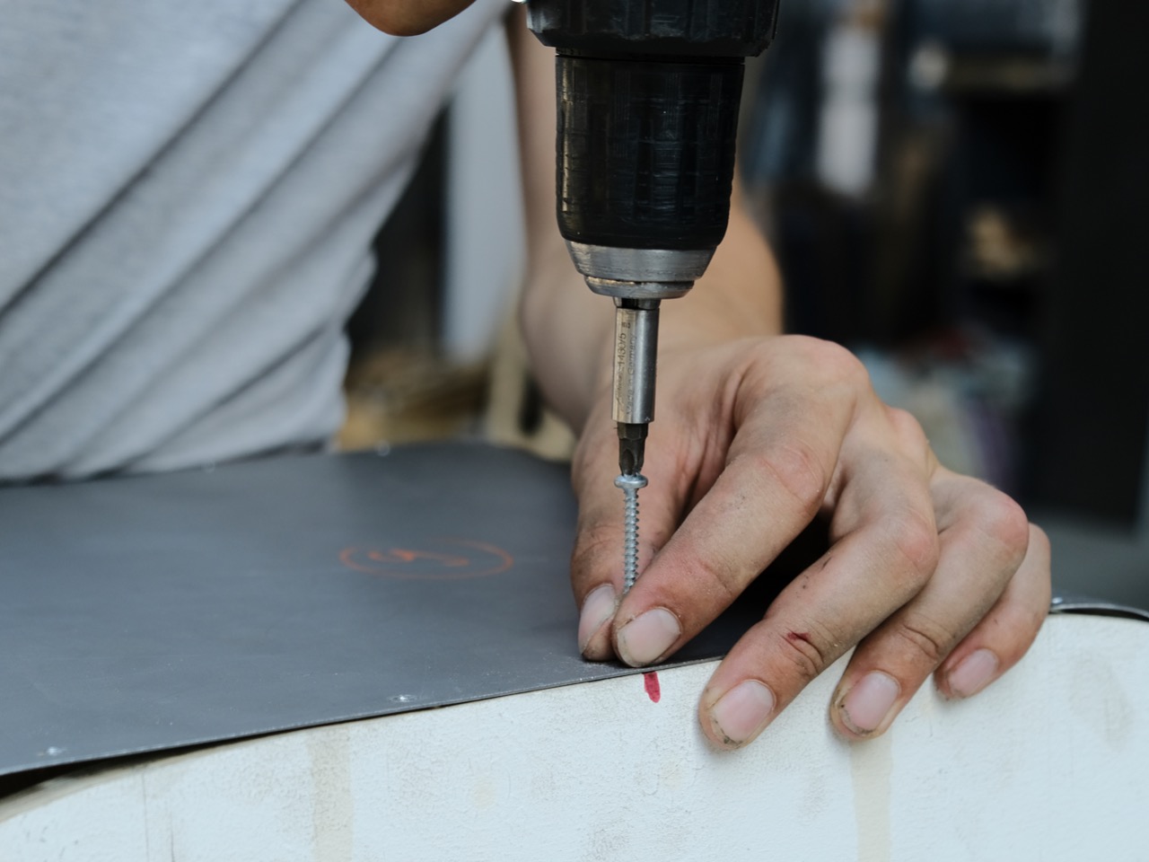
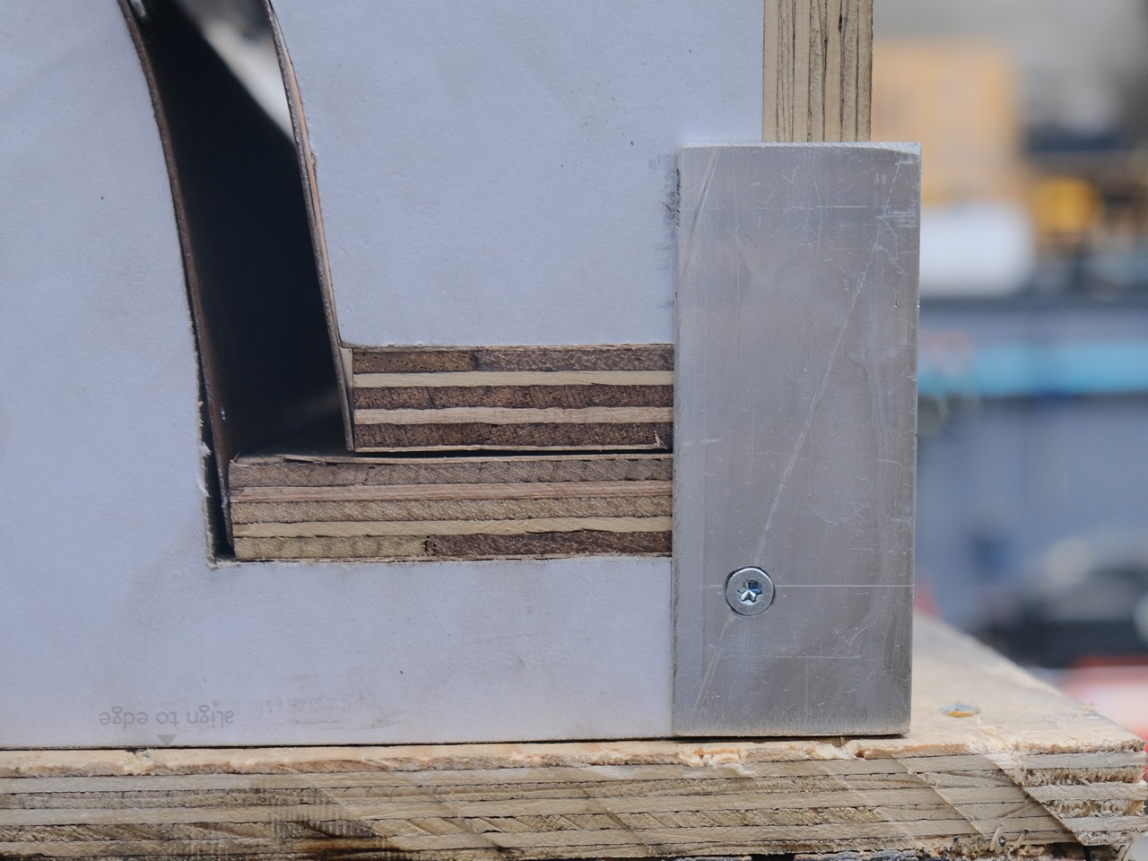
Screw together as you planned before. In most of the materials you should pre-drill to avoid cracking! Hence it’s a lot faster to use two cordless drills at the same time. Don’t put the wedges to the positive mould, you will need them in step 9.
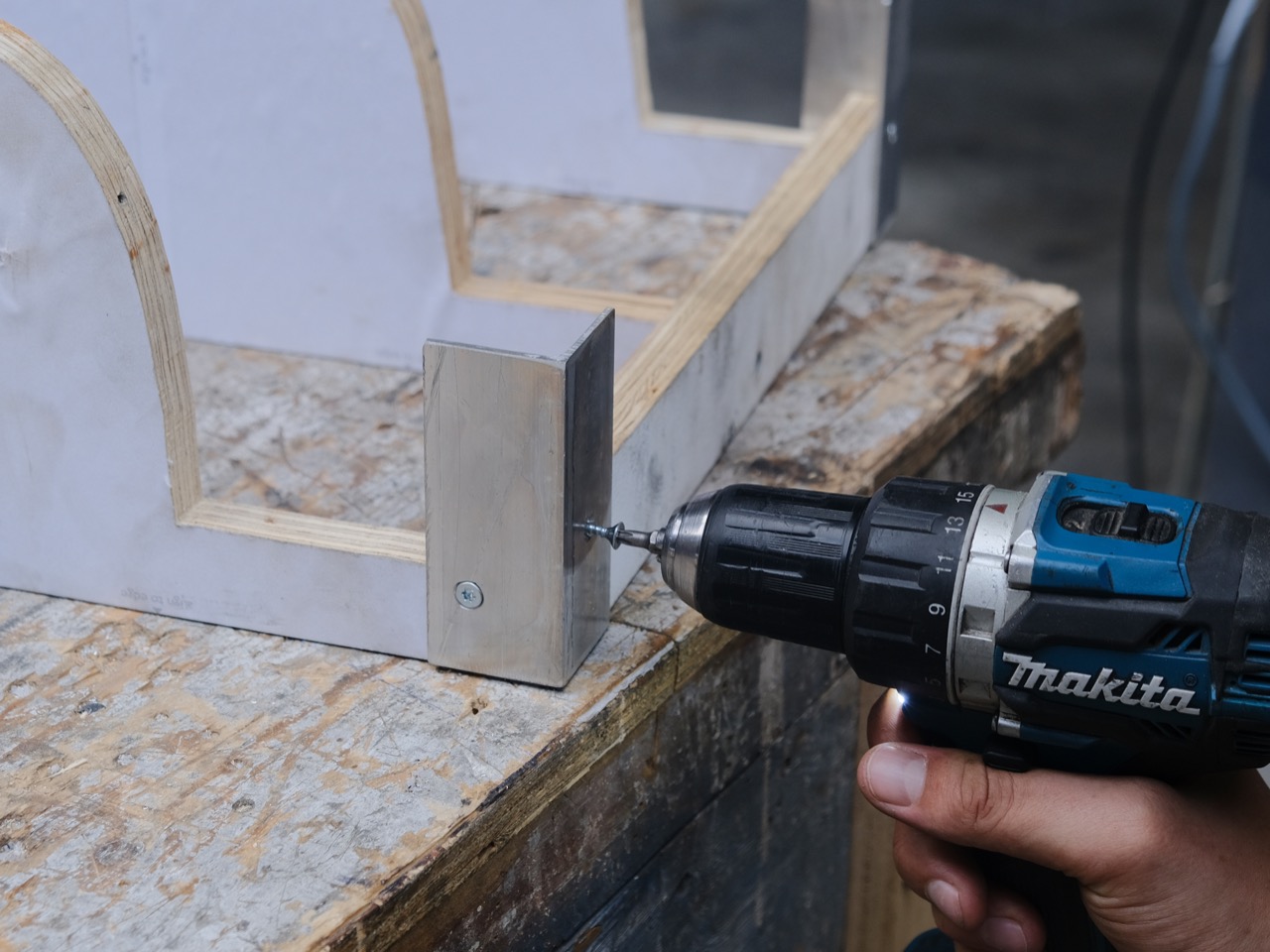
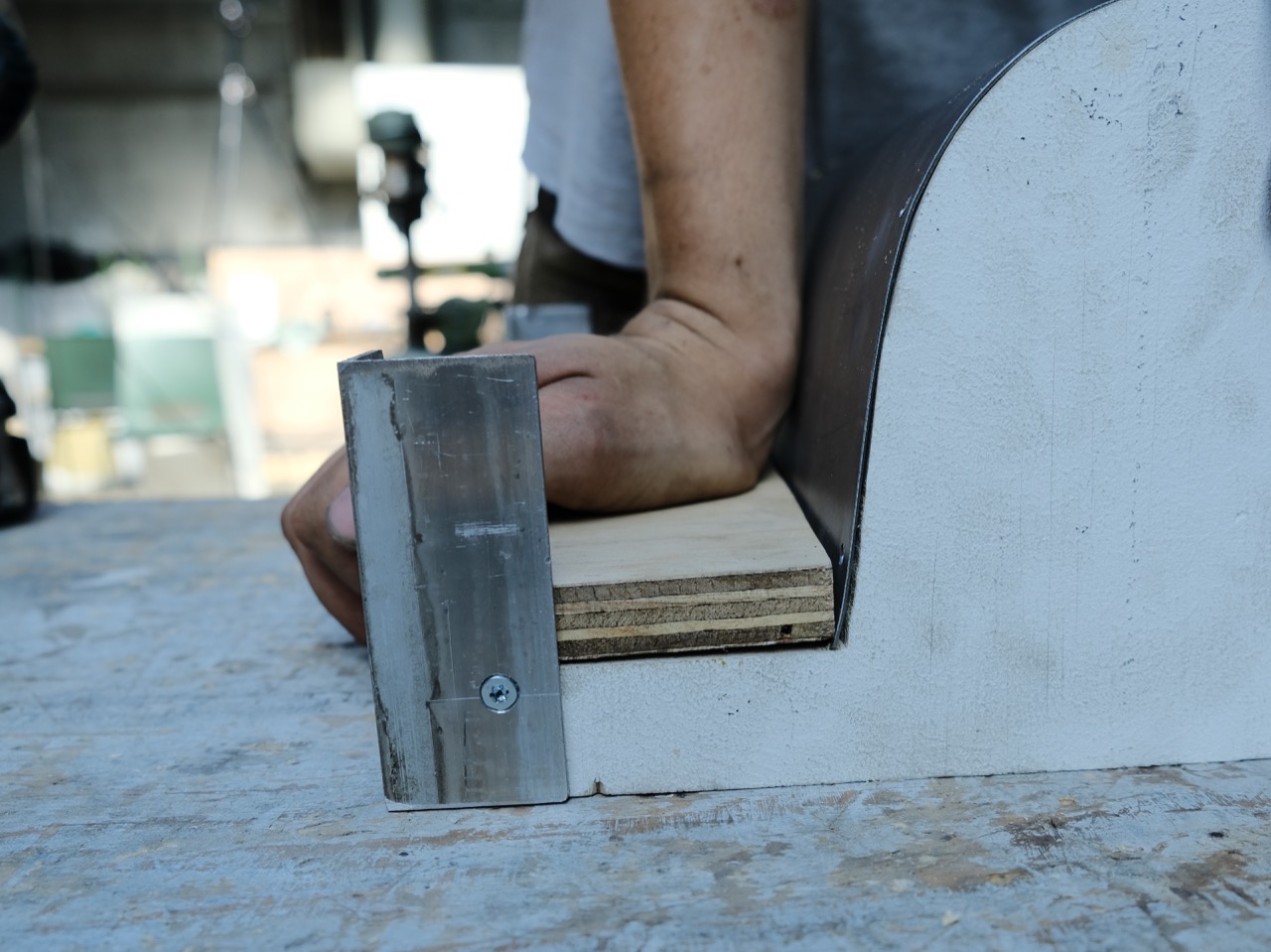
As well attach some guides like aluminium L-bar to the corners in order to align the two halves more easily later. While doing so, place both halves on top of each other to make sure the whole frame is square.
As well attach some guides like aluminium L-bar to the corners in order to align the two halves more easily later. While doing so, place both halves on top of each other to make sure the whole frame is square.
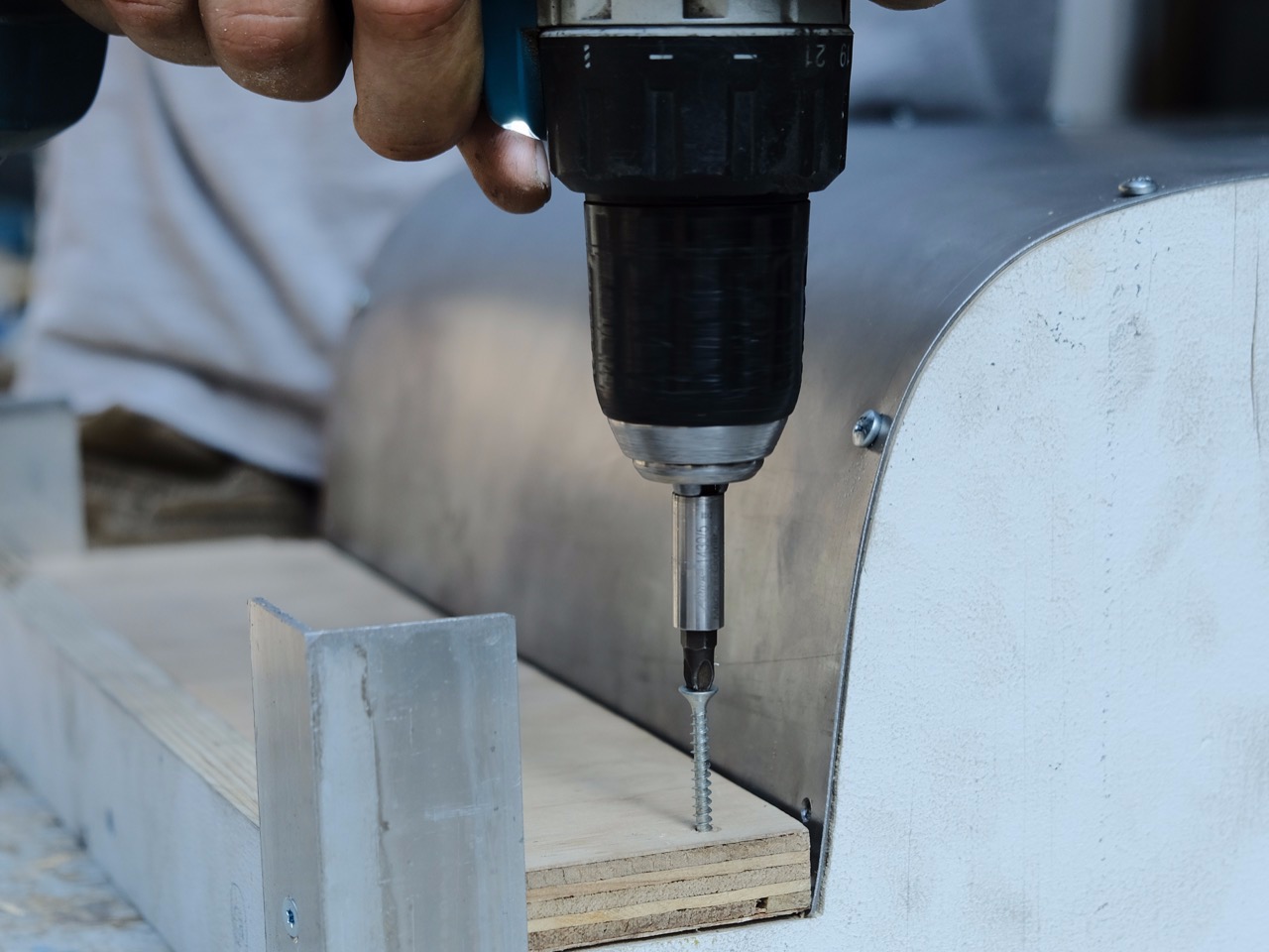
Step 8 - Making the positive mould: screws
Mark the centerline on the sheet metal, align it to the frame and attach it with screws. Then bend it downwards around the curvature and fix it every once in a while.
Step 9 - Making the positive mould: wedges
As soon as you’re close to the end, you can use the previously cut pieces to wedge the sheet metal in place. Fix those wedges with care as they are under a constant tension and might flip out.

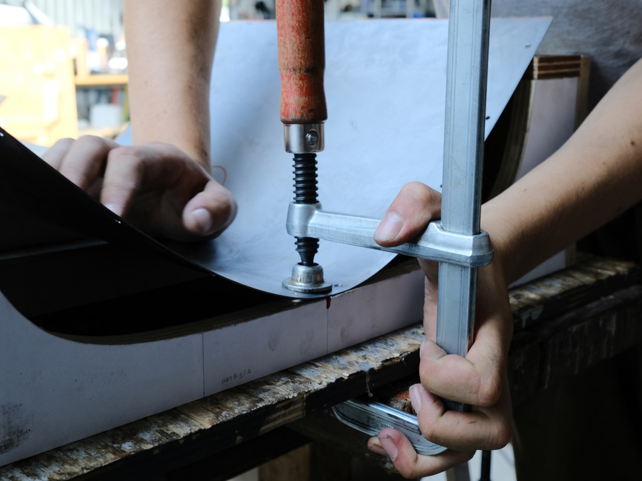
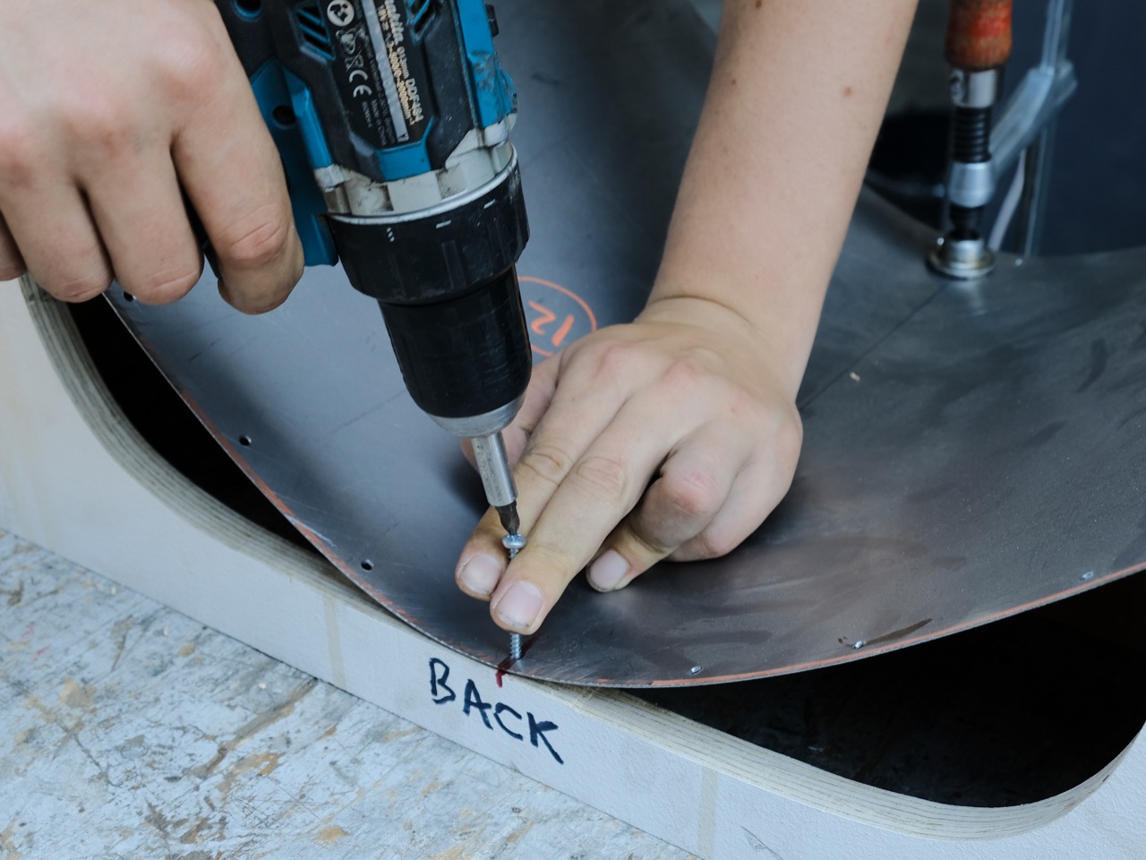
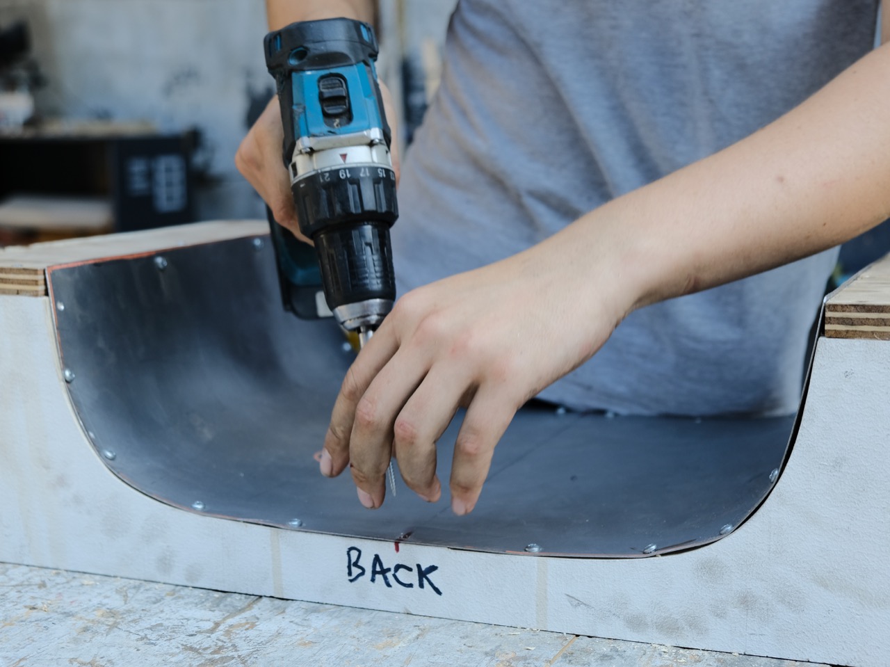
Step 10 - Making the negative mould: screws
The process is pretty much the same as for the positive mould, you start as well from the middle. Here, you just have to clamp the sheet metal down first and attach it in the middle. Then again, go outwards, the only difference is that no wedges are necessary.
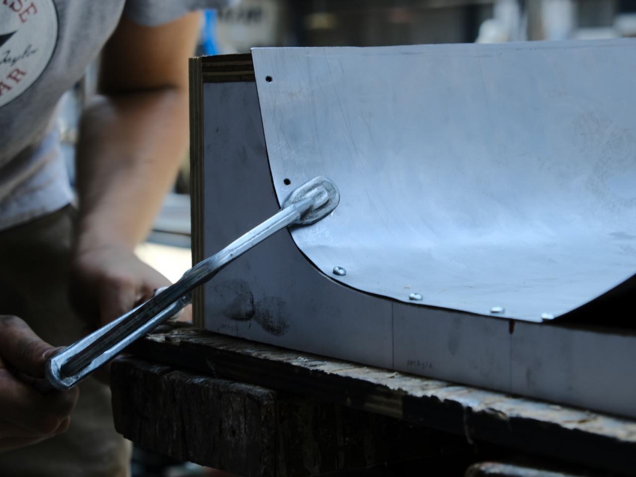
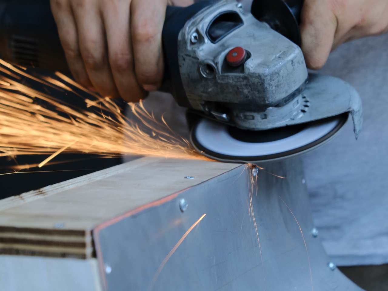
Step 11 - Making the negative mould: trim
In case the sheet metal exceeds the curvature’s length, you can easily grind it off. It’s crucial that the flat wedges of both halves come nicely together, otherwise the offset is not right and might deform your plastic sheet.
Step 12 - Cut guides
When it comes to the bending, you’re handling a 200°C hot piece of malleable plastic, so you really want to make it as quick as possible. A guide can help you to align the piece within the mold. In this case we simply use the off-cuts from step 5. Cut them to the right length and remove the screws from the mould on both halves where you want to put the guide. The sheet metal will still stay in shape thanks to the tension.

Step 13 - Attach guides
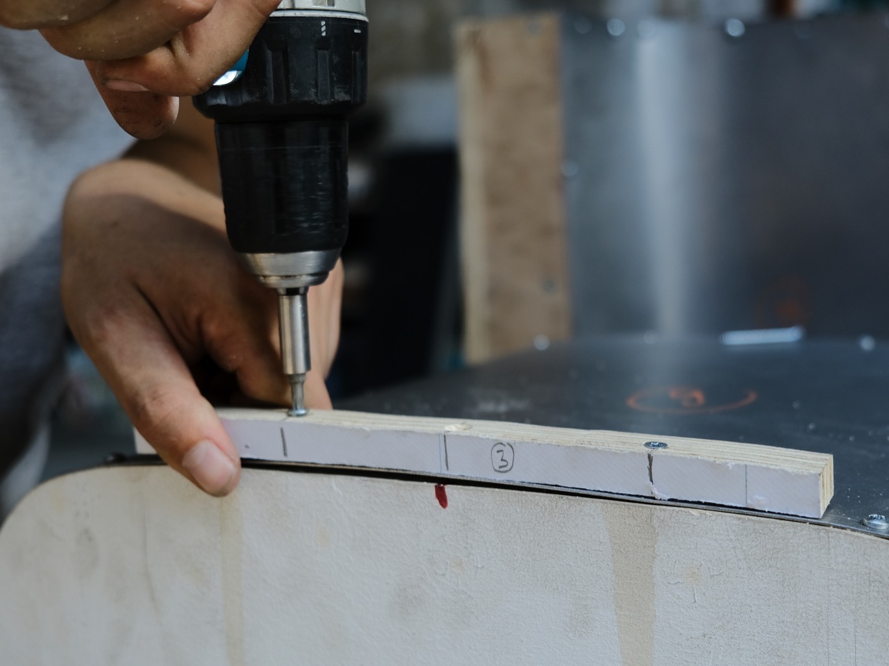
Then mark the position of the screws, pre-drill and countersink the holes. Screw through the holes and the sheet metal into the cross-section using countersunk screws. Again, the screws should fully immerse in the material as the opposite half must not interfere with them.
Step 14 - Ready to bend some sheets!
Good job, you’re done! For the usage of your brand new mould, check out 👉 tiny.cc/bend-plastic-sheets.
—
—
—
Comments