Make a lightswitch and socket
Making decorative objects and handcrafts is one thing, but is recycled plastic capable of replacing industrially manufactured and standardized components? The lightswitch and socket proof that!
—
Attachments
Resources
3D Files
- 3D Step File: /files/Socket_Switch/Mould_Socket-Side_A.STEP - Preview
- 3D Step File: /files/Socket_Switch/Mould_Socket-Side_B.STEP - Preview
- 3D Step File: /files/Socket_Switch/Mould_Switch-Frame-Side_A.STEP - Preview
- 3D Step File: /files/Socket_Switch/Mould_Switch-Frame-Side_B.STEP - Preview
- 3D Step File: /files/Socket_Switch/Mould_Switch-Insert-Side_A.STEP - Preview
- 3D Step File: /files/Socket_Switch/Mould_Switch-Insert-Side_B.STEP - Preview
- 3D Step File: /files/Socket_Switch/Part_Socket.STEP - Preview
- 3D Step File: /files/Socket_Switch/Part_Switch-Frame.STEP - Preview
- 3D Step File: /files/Socket_Switch/Part_Switch-Insert.STEP - Preview
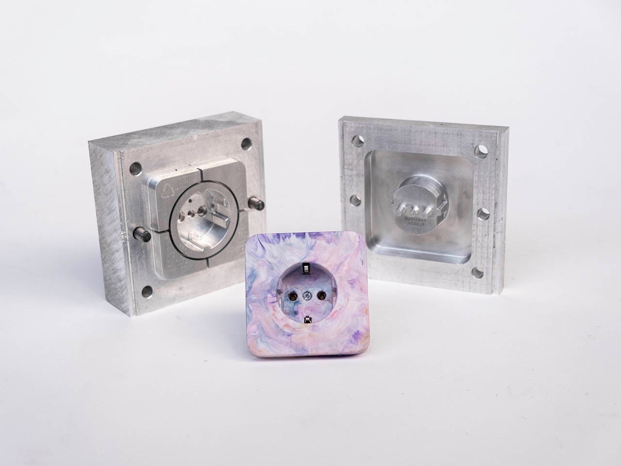
Step 1 - Make the moulds: CNC
Those pieces will be injected, so you need the moulds and access to an Injection machine.
For the mould-making, download the files above and CNC-mill it yourself or send it to a mould maker.
In the latter case, make sure to communicate clearly if your part is designed as the resulted part or already oversized to compensate for shrinkage. The file attached above is the actual size of the end result, so you need to scale it depending on your material. For the PP we used we scaled the model up by 2,6%.

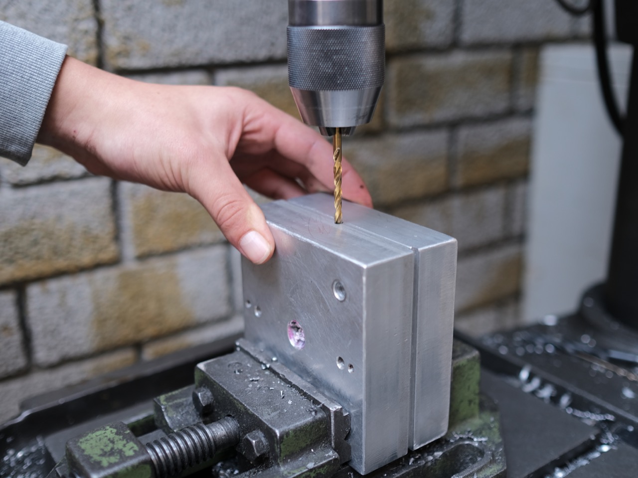
Step 2 - Make the moulds: Sliders
The lightswitch cover needs holes for sliders to achieve a snap connector feature which shapes an undercut.
Drill the corresponding holes perpendicular to the unmoulding direction and use a tightly fitting pin (e.g. the back of the drill or a parallel pin) as slider.
Drill the corresponding holes perpendicular to the unmoulding direction and use a tightly fitting pin (e.g. the back of the drill or a parallel pin) as slider.

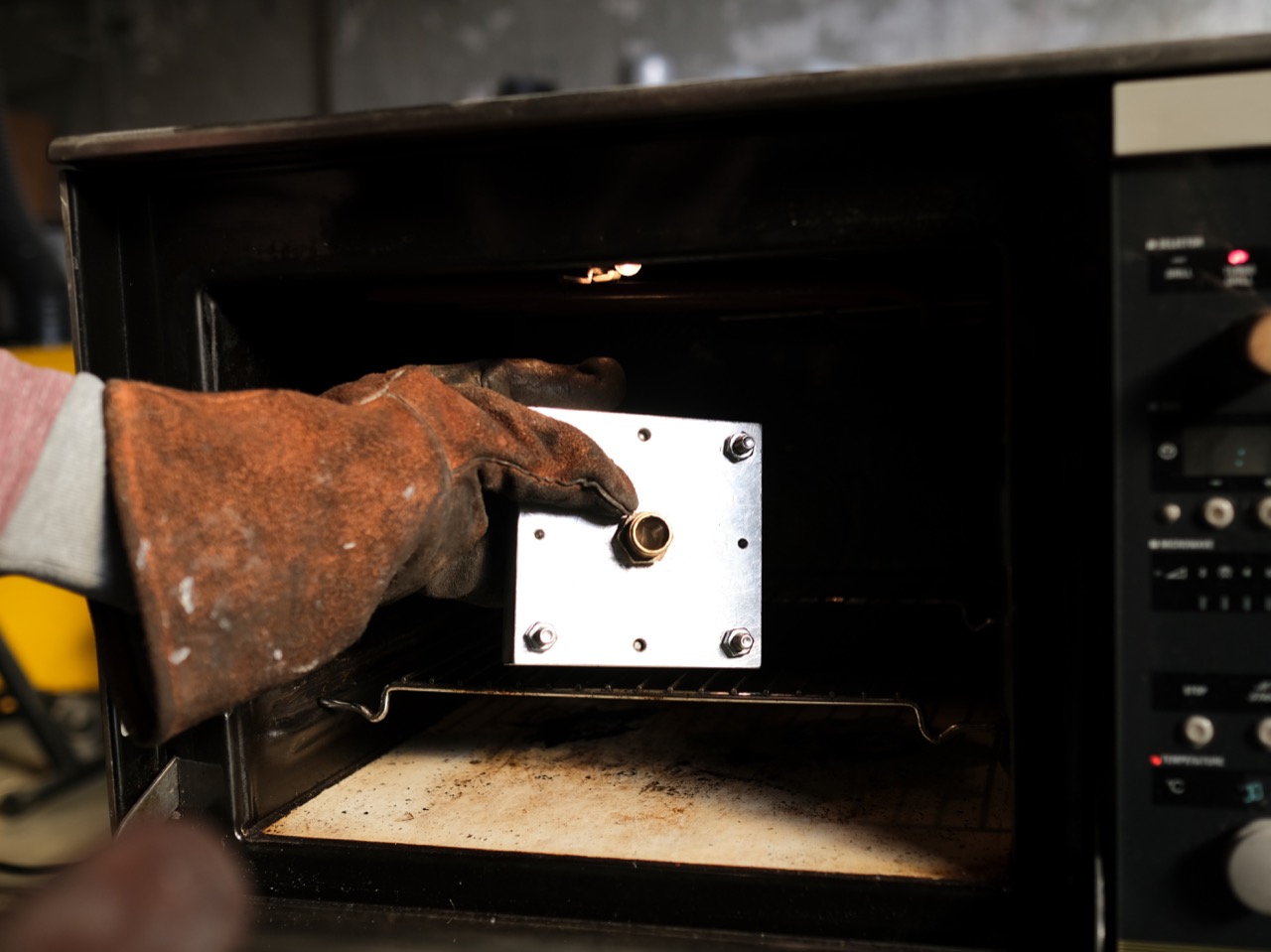
Step 3 - Preparations
Due to the very thin walled diaphragm injection gate, preheating the lightswitch frame’s mould makes the process of injecting easier. The amount of plastic needed for all parts is about half a barrel, but rather work with a full barrel to ensure enough pressure.
As the mould is quite intricate and detailed, a plastic with good flow characteristics is required.
e injected PP on 270/280°C (barrel/nozzle), but a few tests might be necessary to calibrate your machine.
As the mould is quite intricate and detailed, a plastic with good flow characteristics is required.
e injected PP on 270/280°C (barrel/nozzle), but a few tests might be necessary to calibrate your machine.
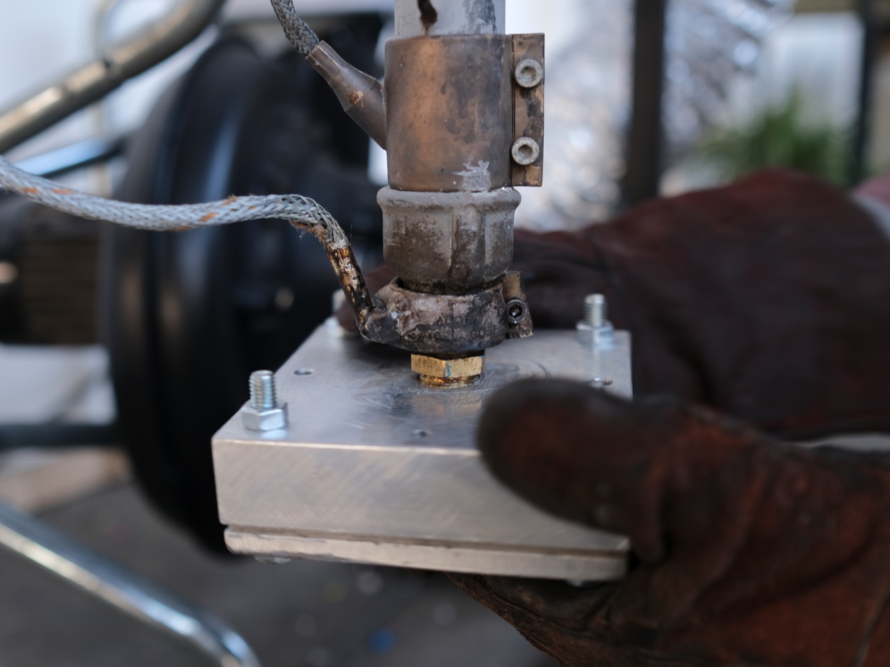
Step 4 - Inject the parts
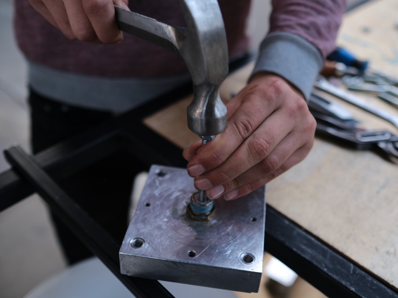
Time to inject. The plastic should be evenly molten to easily spread within the mould, so it might run out of the nozzle just because of gravity. Use a plug that’s screwed into the nozzle and remove it right before you start injecting.
Act fast and keep the pressure for a couple of seconds before lifting the lever. This will prevent sink marks as the plastic is cooling down under pressure.
Act fast and keep the pressure for a couple of seconds before lifting the lever. This will prevent sink marks as the plastic is cooling down under pressure.

Step 5 - Unmould your parts
Once injected, you can take out the sliders and open the mould. You don’t need to wait additionally for the plastic to cool down, the time it takes to open the mould is a sufficient cooldown time.
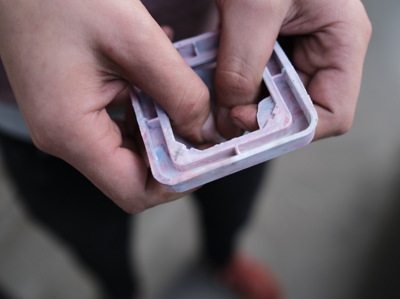
Especially the lightswitch cover sits pretty tightly in the mould and levering with a spatula is needed. It helps much to lift the part evenly from each side to eject the parts.
Take care that you don’t scratch the mould cavity with metal tools.
Especially the lightswitch cover sits pretty tightly in the mould and levering with a spatula is needed. It helps much to lift the part evenly from each side to eject the parts.
Take care that you don’t scratch the mould cavity with metal tools.

Step 6 - Finish
Break the injection point along the predetermined breaking points. If necessary use a knife to shave off excess material.


Step 7 - Mount it and love it!
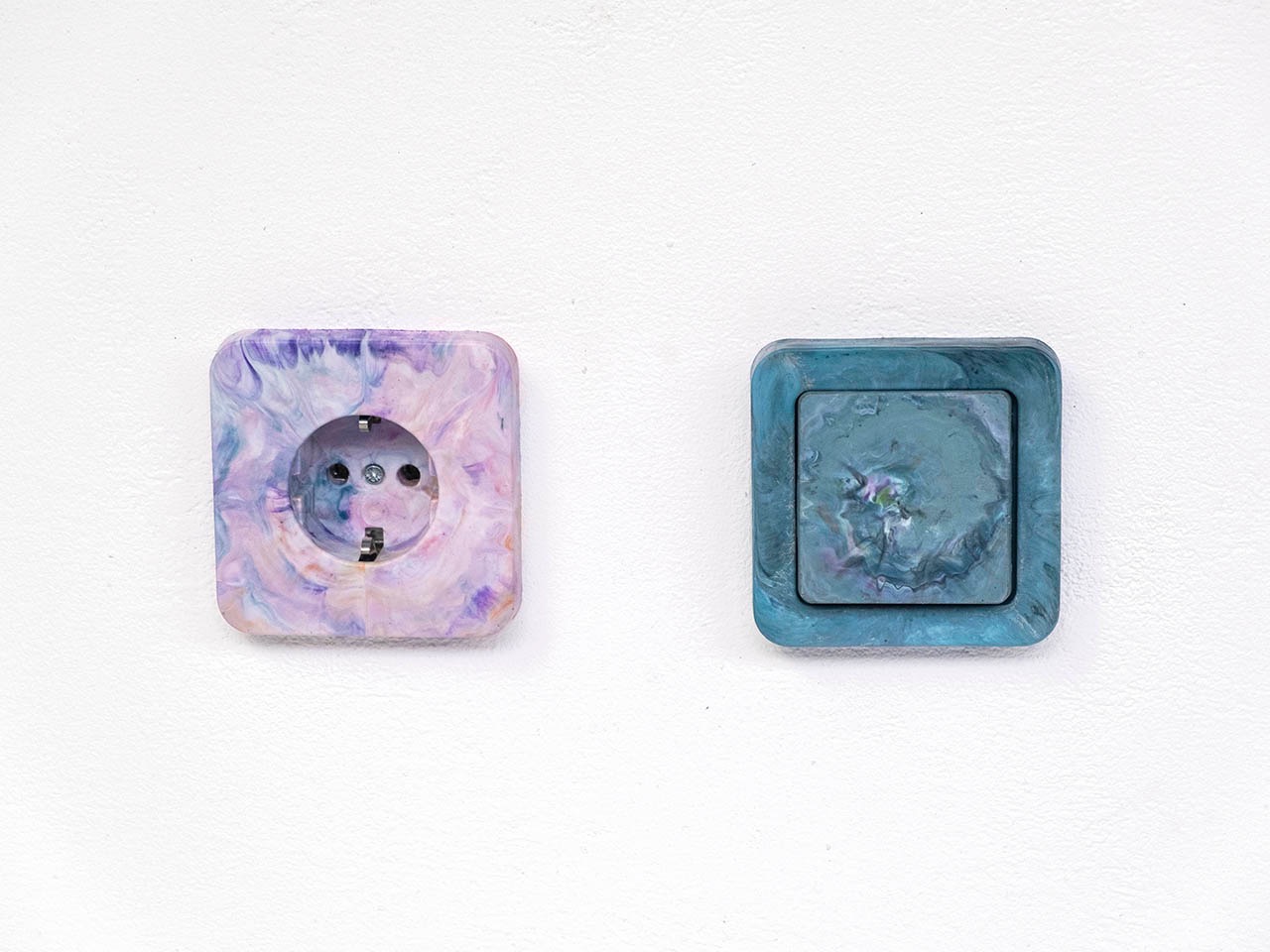
Your parts are ready!
Keep in mind that this product is in direct contact with high voltage electricity, so don’t try to mount it yourself unless you’re qualified.
Should one of the parts break, you can simply shred and melt it again, or bring it to another Precious Plastic workspace where they can recycle the plastic. :)
—
—
—
Comments