Make the ‘Plástico Fantástico’ Recycling Bicycle Shredder
by OSR-Plastic
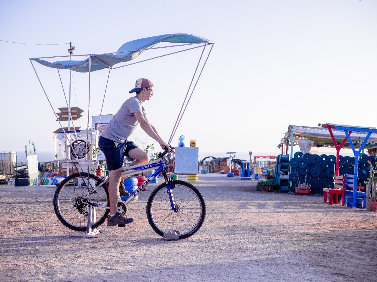
The adapted bicycle shredder combines the power of shredding with the joy of cycling so you can collect and shred plastic ready for moulding as you travel from place to place. The adaptation has taken influence form Precious Plastic Shredder that was adapted for use on a bicycle.
For more information about the adaptation please reach out via Instagram to ‘@jam_goreing’
Or see the 3 minute project video at (https://www.youtube.com/watch?v=IoSn84Axao8)
—
Attachments
Resources
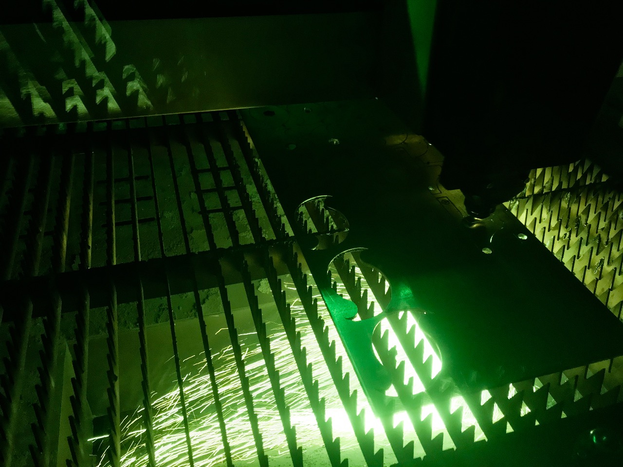
Step 1 - Create the Shredder and Housing
The basic design and instructions for the shredder can be found on the Precious Plastic Instruction pages (https://community.preciousplastic.com/academy/build/shredder).
Initially the number of shredder blades will need to be reduced down to around 9 from the original design so that the shredder is thin and light enough to be mounted on the back of a bicycle, however more can be incorporated if desired. The depth of the shredder housing will then need to be scaled down in co-ordination with the reduced number of blades.
For the housing, aluminium or steel can be used so long as the blades and spacers are still made of steel. Using aluminium will mean that the housing has to be bolted together instead of welded.
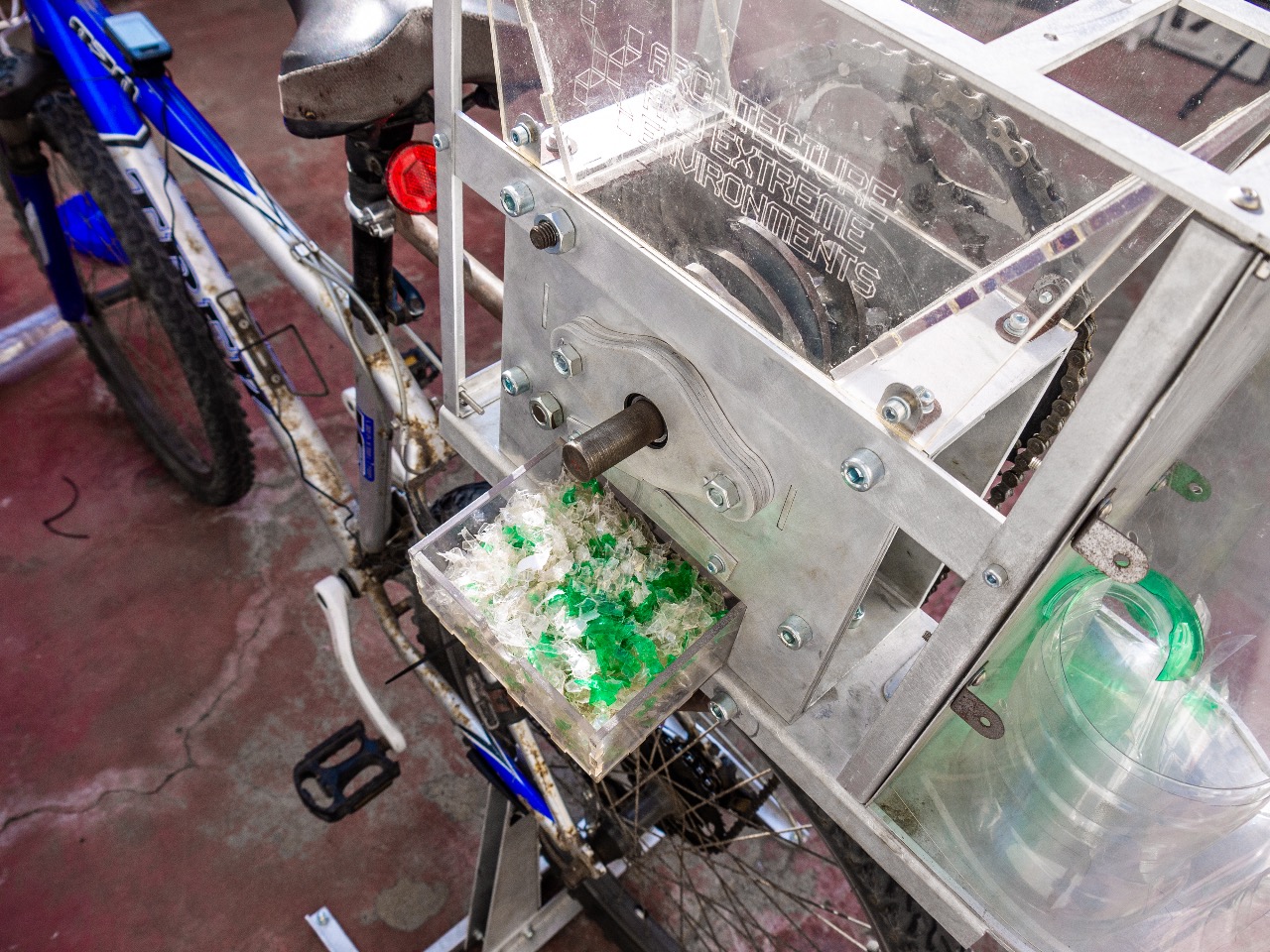
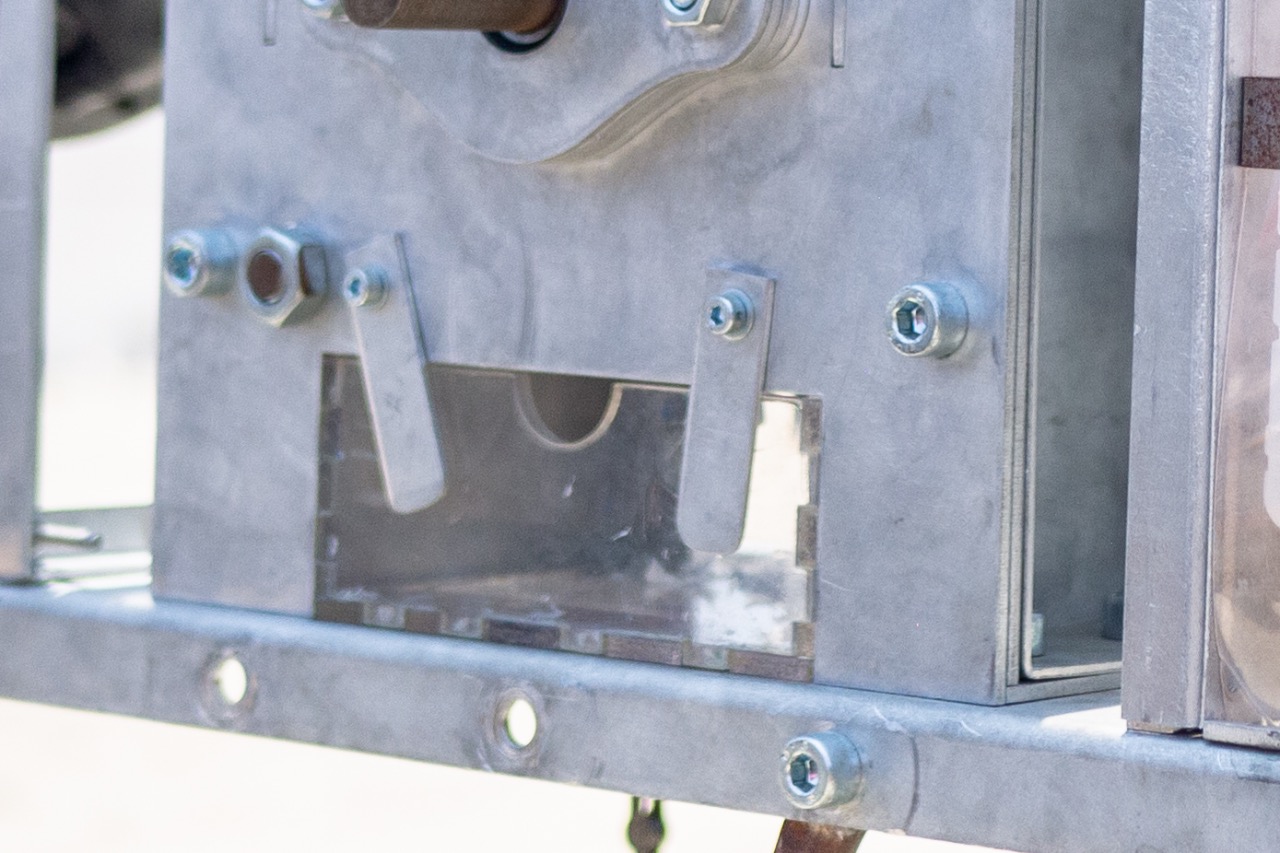
Step 2 - The Plastic Collection Tray
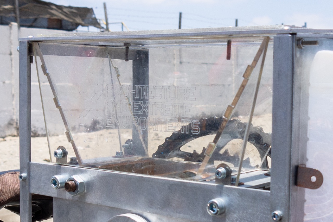
The housing will need to be elongated downwards to allow for a collection tray for the shredded plastic that can sit underneath the shredder blades. The housing needs to be elongated down around 50mm allowing a space in the middle for the collection tray as illustrated in the images. The collection tray itself is made of clear acrylic that then slots together.
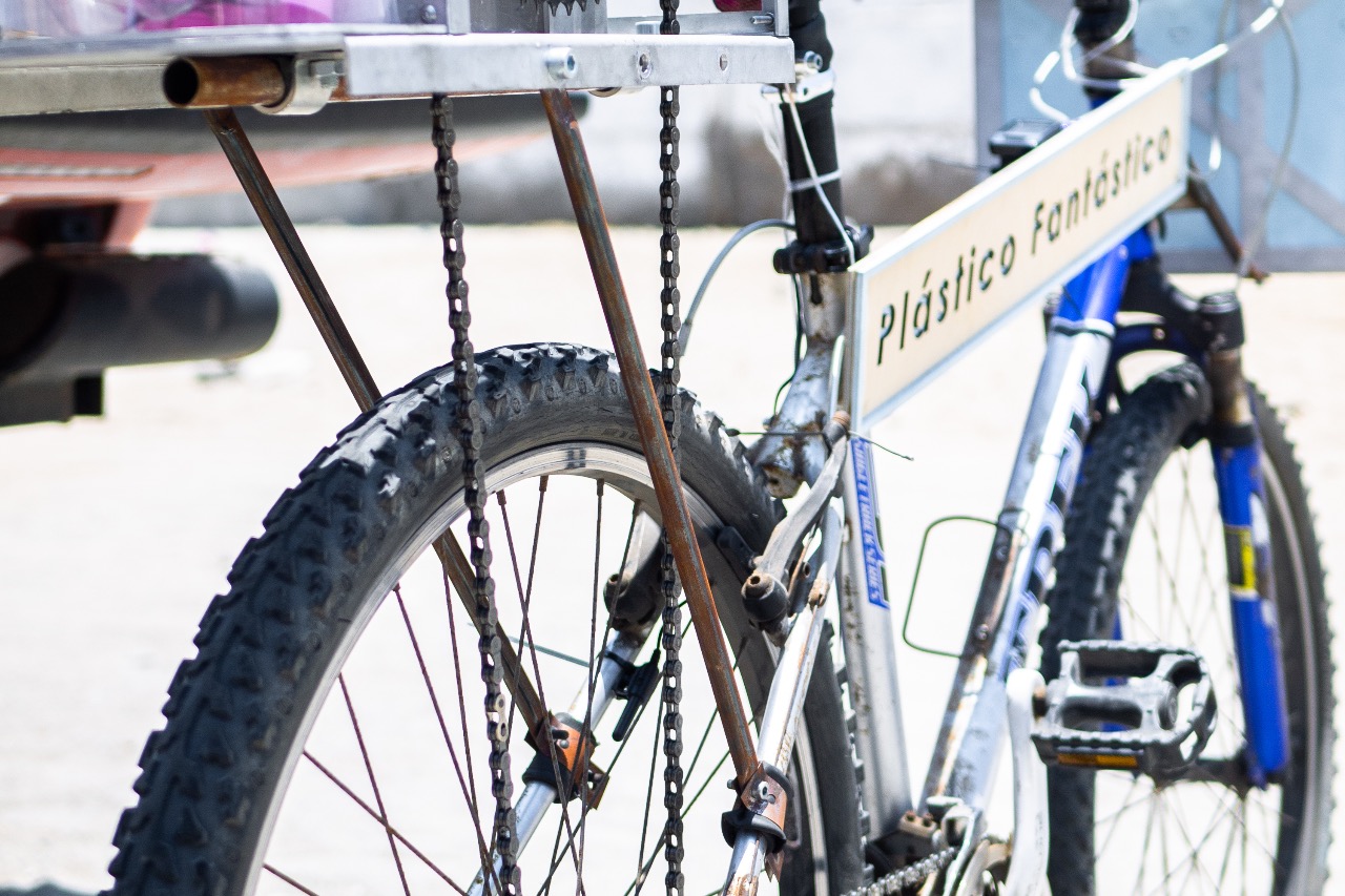
Step 3 - Create the Shredder Support Base
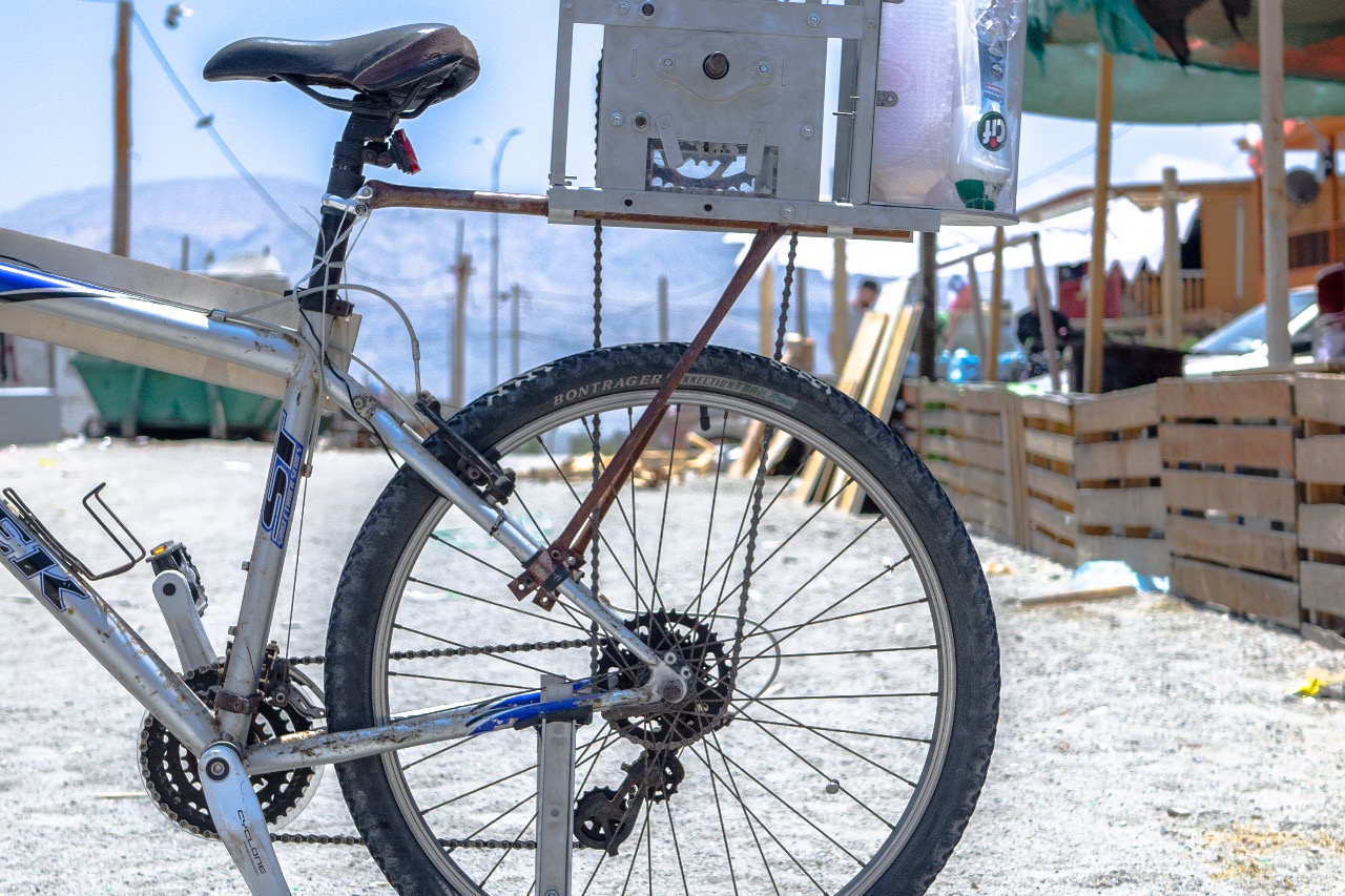
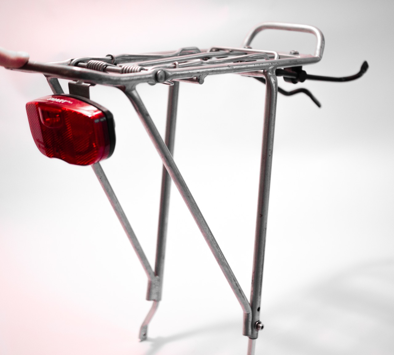
The shredder will need a solid base to sit for when it is attached to a bicycle to allow for the weight of the shredder and the force placed upon it when shredding. In most circumstances a traditional bicycle back rack will be sufficient for this task, the back rack can be mounted to the bike and then adapted to secure the shredder.
During my experiment I did not know exactly which bicycle I was going to use, as I planned to rent one when I reached the project testing location of Chile. Due to this I had to create a support frame that would fix to a variety of bicycles.
During my installation the shredder sat on an aluminium support base that had three steel rods bolted to it to create the supporting connection to the bicycle. The central steel rod was attached to the Seatpost via a second Seat Collar around the Seatpost. The two side rods attached to the Seat Stray and at the end of each rod a 0.5mm thickness steel plate was connected that could be wrapped around the frame by hand. An old inner tube acted as a rubber lining to fix the support frame to the bicycle and stop it sliding down.
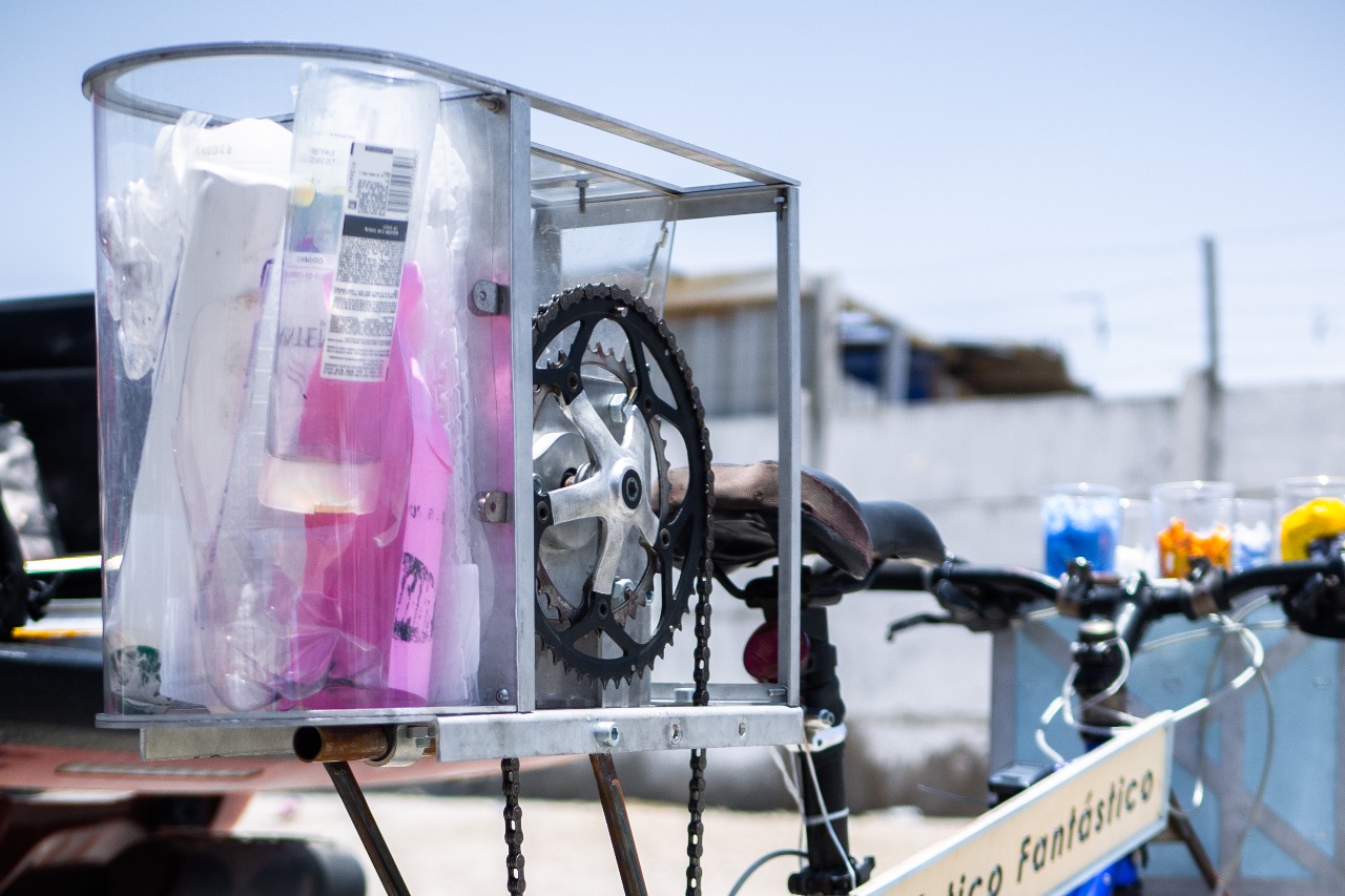
Step 4 - The Hopper Frame
The hopper is made of clear acyclic along with the shredded plastic collection tray, located under the blades. The hopper will need to be bolted to the top of the shredder housing to lock it in place. A simple aluminium-casing frame can be built around the hopper for aesthetic purposes. This can incorporate at the rear, storage for all the collected waste plastic before it is shredded. Alternative designs can be implemented, as this does not affect the shredding ability or the stability of the hopper.

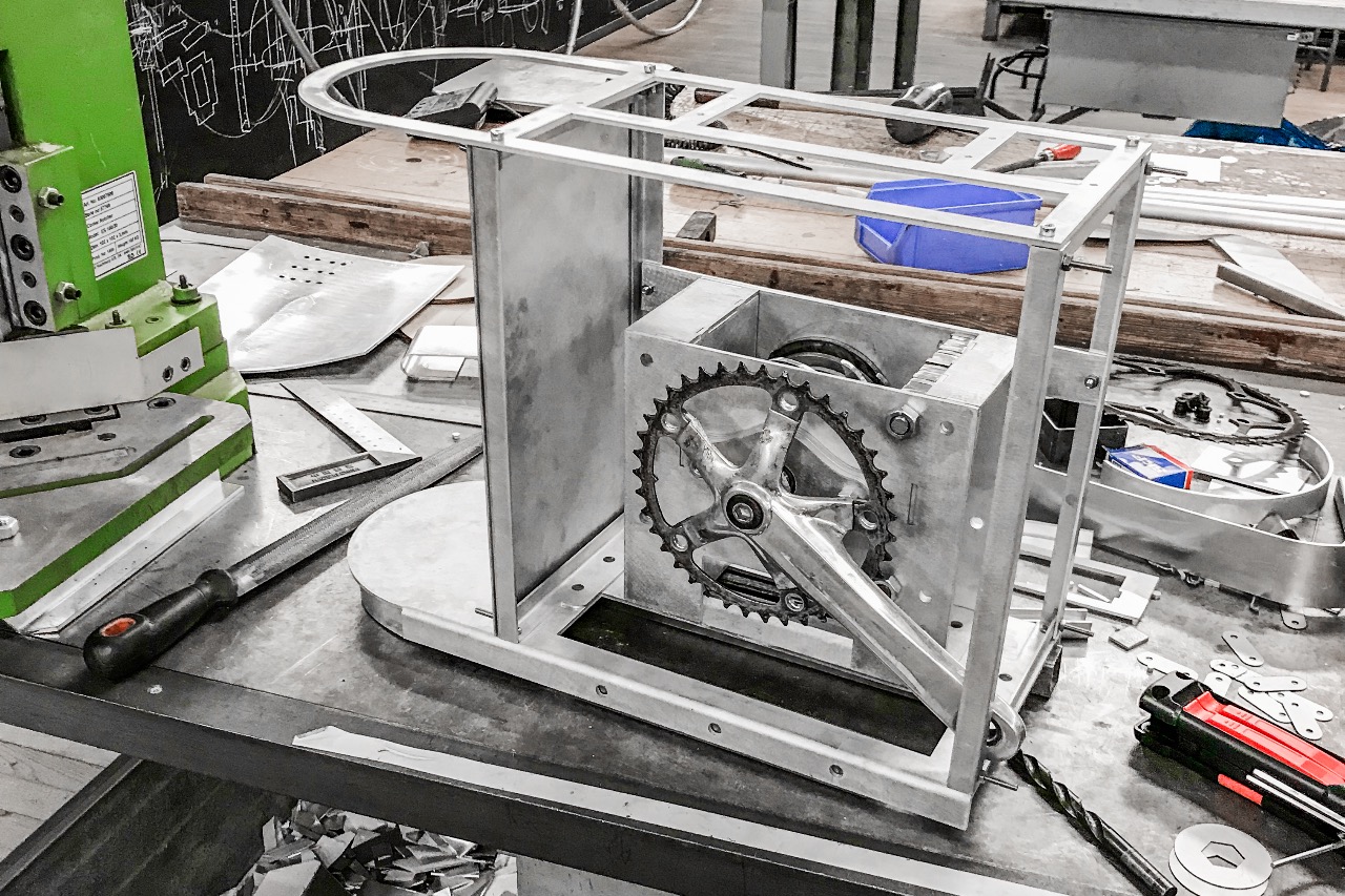
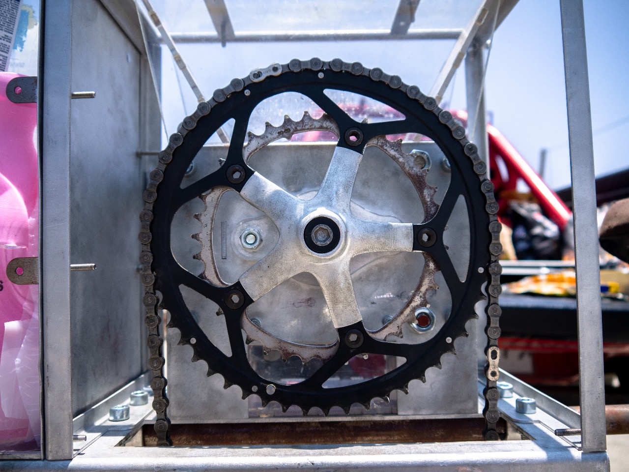
Step 5 - Gears and Ball Bearings
A used bicycle square taper bottom bracket and corresponding crank and crank bolt will need to be acquired to be able to attach the gear to the shredder. The steel square tapered end of the bottom bracket is first cut off with an angle grinder.
A sealed ball bearing will be needed to allow the blades to spin on the axle. The ball bearing needs to allow the thickest end of the taper to fit through it. In my case the square taper had a maximum diameter of 16mm and so a sealed ball bearing with an inner diameter of 17mm was used.
A sealed ball bearing will be needed to allow the blades to spin on the axle. The ball bearing needs to allow the thickest end of the taper to fit through it. In my case the square taper had a maximum diameter of 16mm and so a sealed ball bearing with an inner diameter of 17mm was used.
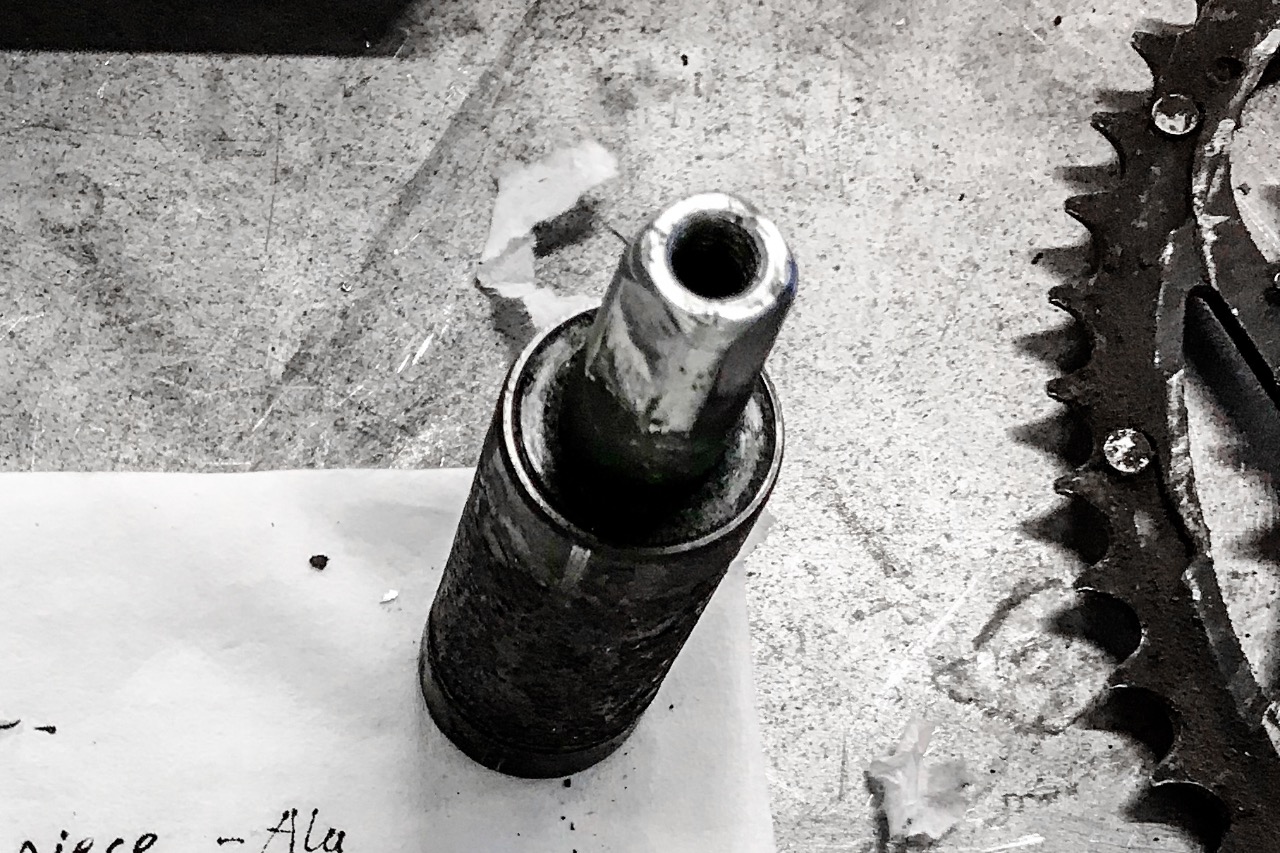
Step 6 - Preparing the Blade Axle
The axle for the blades is as per the Precious Plastic instructional video; a hexagonal axle that is lathe down to be round at either end. The axle is lathe down at either end to be the same diameter as the inner diameter of the ball bearing. It is important to ensure there is no gap between the axle and the ball bearing when they are fitted together.
The very end of the now rounded axle (last 5mm) then has to be lathe down further to the diameter of the crank bolt thread. The cut off square taper is already threaded all the way through the centre and so the axle (once lathe down to the thread thickness) can sit within this to centre the square taper on the axle ready for welding.
The very end of the now rounded axle (last 5mm) then has to be lathe down further to the diameter of the crank bolt thread. The cut off square taper is already threaded all the way through the centre and so the axle (once lathe down to the thread thickness) can sit within this to centre the square taper on the axle ready for welding.
Step 7 - Attaching the Gear
Next, the cut off square taper will need to be welded onto the axle. Once the square taper is welded on and lathe down so that it can be thread back through the ball bearing the gear can be attached using the crank bolt to hold it tightly in place.
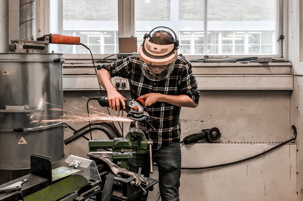
The crank arm will need to be cut off using an angle grinder, then again using the angle grinder the crank can be shaped to smooth it back and create a formed shape.
The crank arm will need to be cut off using an angle grinder, then again using the angle grinder the crank can be shaped to smooth it back and create a formed shape.
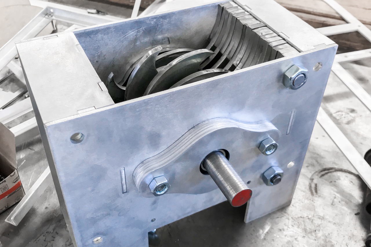
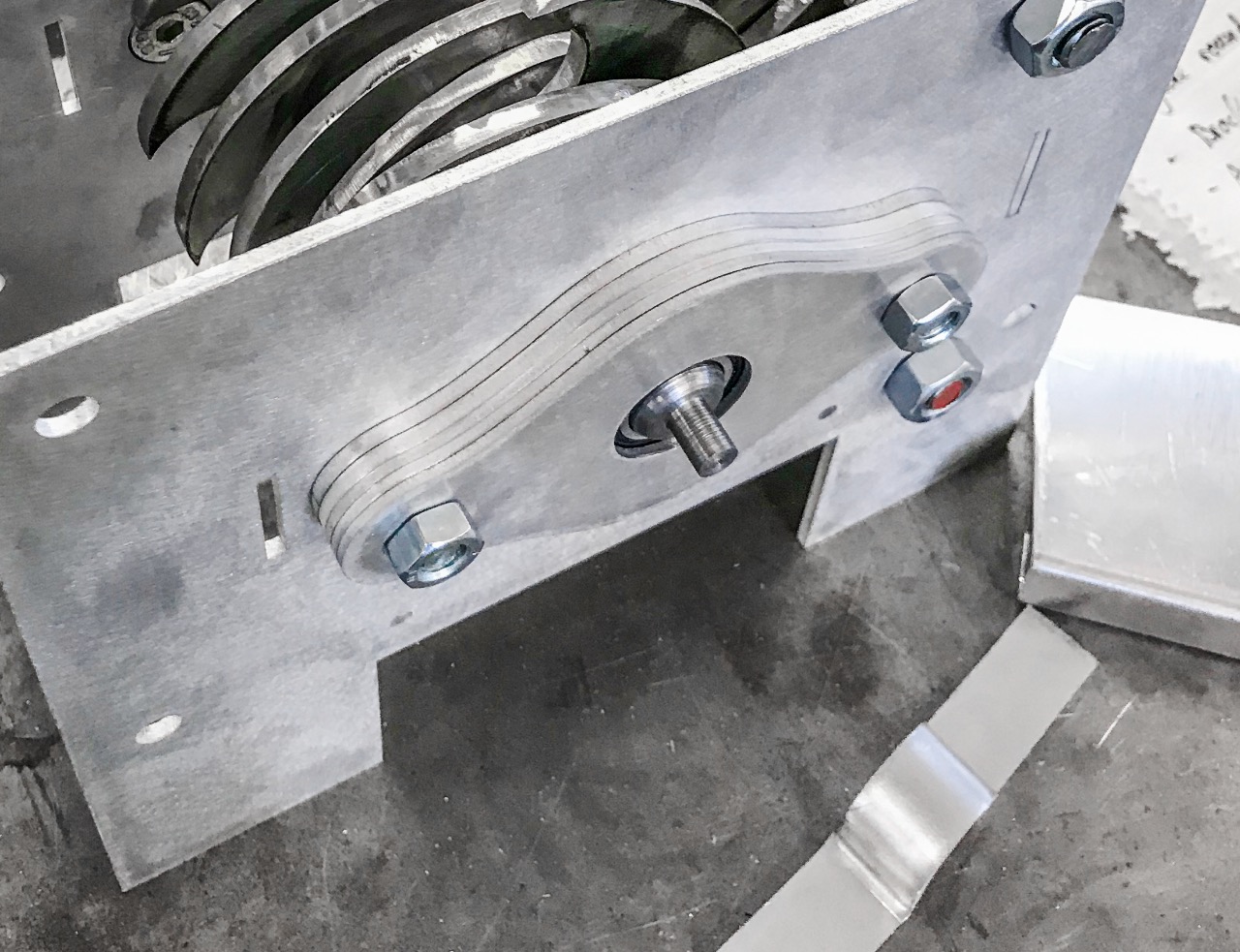
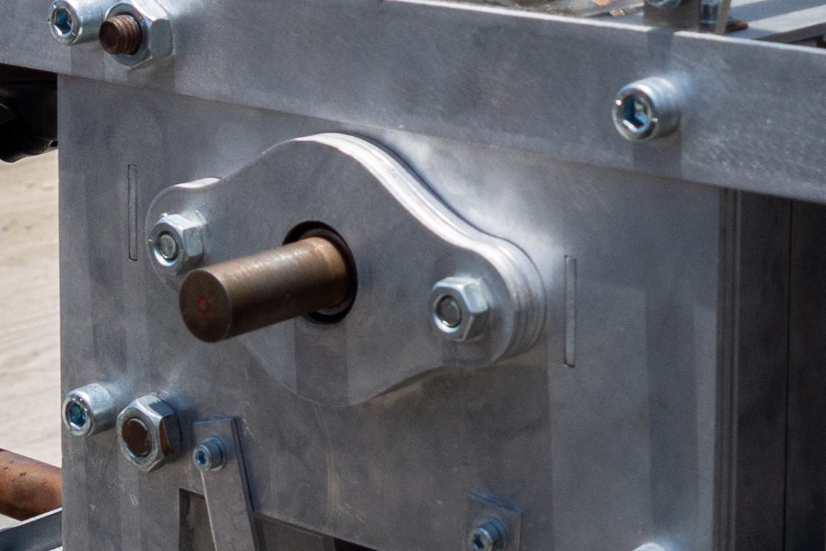
Step 8 - Securing the ball bearing in place
A ball bearing housing will need to be made to securely hold the ball bearing and therefore the axle in place. The ball bearing housing will need to be made of layers of laser cut aluminium or steel where the total thickness of all the layers equates to the thickness of the ball bearing and has a circular hole cut which is the same diameter as the outside diameter of the ball bearing to hold it securely in place. An end cap with a diameter in-between the inside and outside diameter of the ball bearing will also be needed to stop the ball bearing sliding out. Any shape can be made as long as it is attached to the shredder housing and holds the ball bearing in tight.
I found that I additionally needed 1.5mm spacers on the inside of the ball bearing to stop it moving and keep it locked securely in place.
I found that I additionally needed 1.5mm spacers on the inside of the ball bearing to stop it moving and keep it locked securely in place.
Step 9 - Securing the shredder in place
Once the shredder is assembled with the axle and gear securely connected and the shredder bolted to the support frame the chain and gearing can next be considered.
Step 10 - Attaching the chain
The chain attached to the shredder is the connecting element that allows the bike to shred and so it is important to ensure the gearing is correct and the chain is tight once installed. I used a quick release chain as this allowed me to quickly adjust the chain to the correct length then thread it around the gears before tightening.
In my process I did not use a derailleur to keep the chain tight instead I used the adjust-ability of the support frame to tighten the chain by raising the Seatpost that was connected to the shredder support base and so pulled the shredder up tightening the chain.
In my process I did not use a derailleur to keep the chain tight instead I used the adjust-ability of the support frame to tighten the chain by raising the Seatpost that was connected to the shredder support base and so pulled the shredder up tightening the chain.
Step 11 - 11 - Gears
In regards to gearing I looked to use a ratio 4.6:1 where I had 4.6 revolutions of the crank to 1 revolution of the shredder with the intention to reduce the speed of the shredder but increase the torque. The reality was slightly off, I placed the chain connected to the pedal on the inner gear of the cassette (largest) and the chain attached to the shredder on the outer gear of the cassette (smallest) and this proved to work.
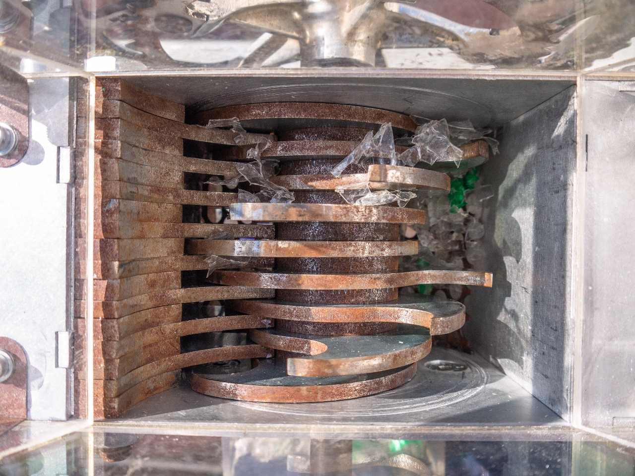
Step 12 - Finishing and Using
Once the shredder is installed and the chain attached its time to use the pedal power to shred some plastic!
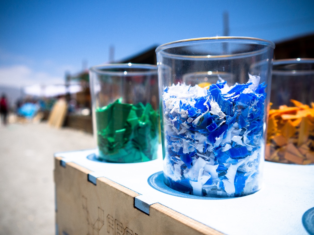
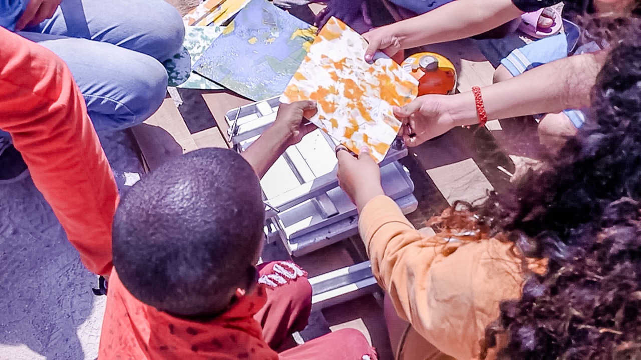
It can be used to shred all sorts of plastic the best proved to be HDPE as this was softer and easier to shred when pedalling. The shredded plastic can then be used to create new plastic inventions such as simple flat cladding panels.
It can be used to shred all sorts of plastic the best proved to be HDPE as this was softer and easier to shred when pedalling. The shredded plastic can then be used to create new plastic inventions such as simple flat cladding panels.

—
—
—
Comments