Make extruded plastic bricks
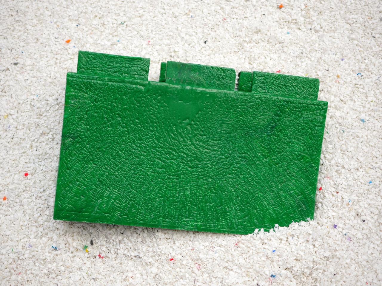
Recycled plastic has the potential to replace more conventional and wasteful building materials such as hollow blocks. In this How-to, you will learn how to assemble the mould for the extruded plastic brick, ready for production.
This brick was developed with the Extrusion Pro machine.
Learn here how to build it:
—
Attachments
Resources
Step 1 - Download templates to send for fabrication
Download the laser cut kit. Then send for fabrication at your local laser cutting service. Note there are three bricks, one full brick and one two-third brick and a one-third brick. All of these are required to build a complete wall.
Before sending to downloaded dwg files to your metal laser cutting service ensure they understand that your drawings are in MM.
Each brick has tolerances included, but may be specific to your supplier. Before ordering, check that the tolerances conform. In this brick, we use a tolerance of 0.5mm.
Before sending to downloaded dwg files to your metal laser cutting service ensure they understand that your drawings are in MM.
Each brick has tolerances included, but may be specific to your supplier. Before ordering, check that the tolerances conform. In this brick, we use a tolerance of 0.5mm.

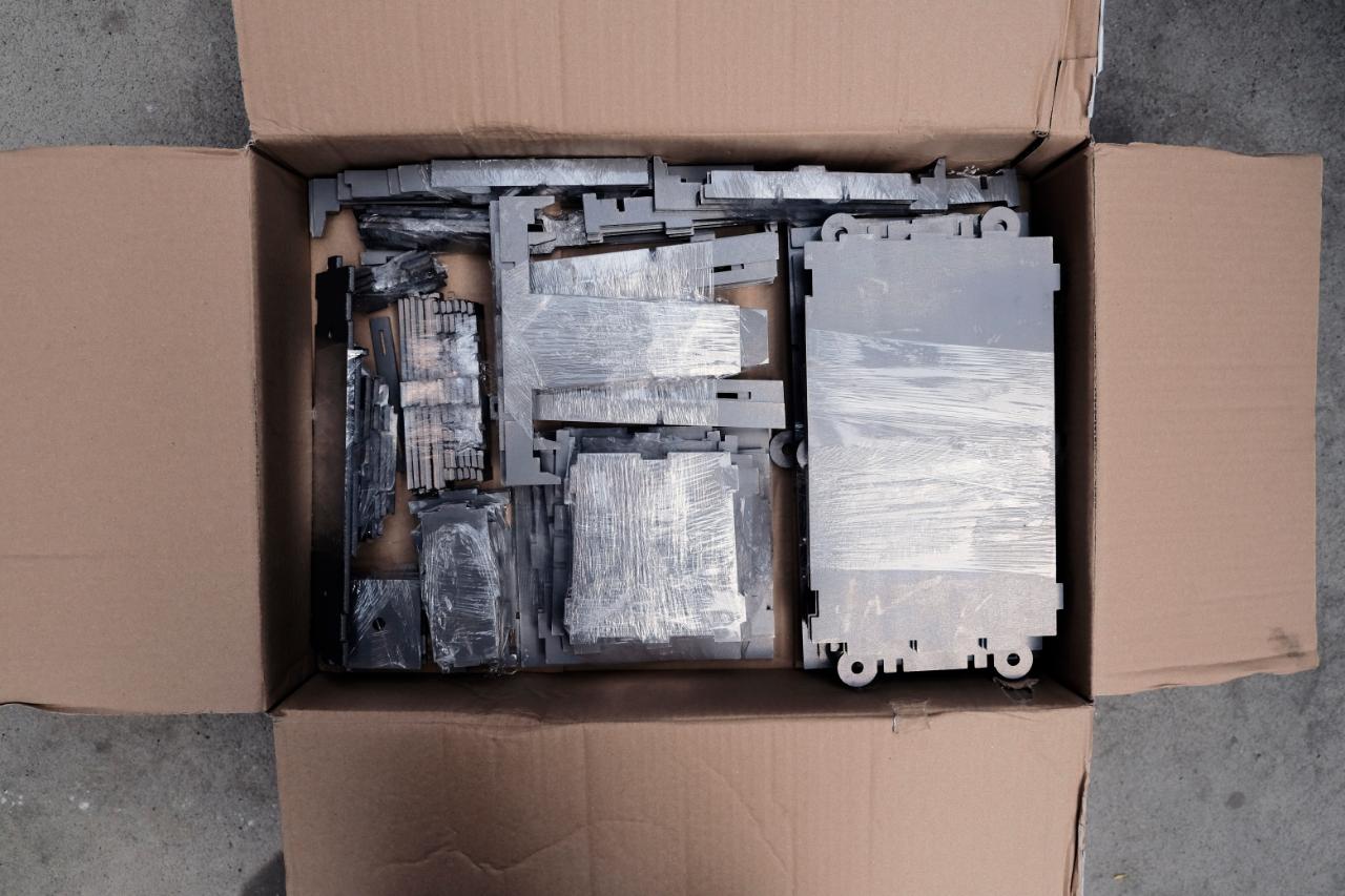
Step 2 - Delivery of laser cut parts
Upon delivery, you should receive various pieces with varying thicknesses. It is good practice to check your parts immediately (compare with drawing) in case any errors have been made.
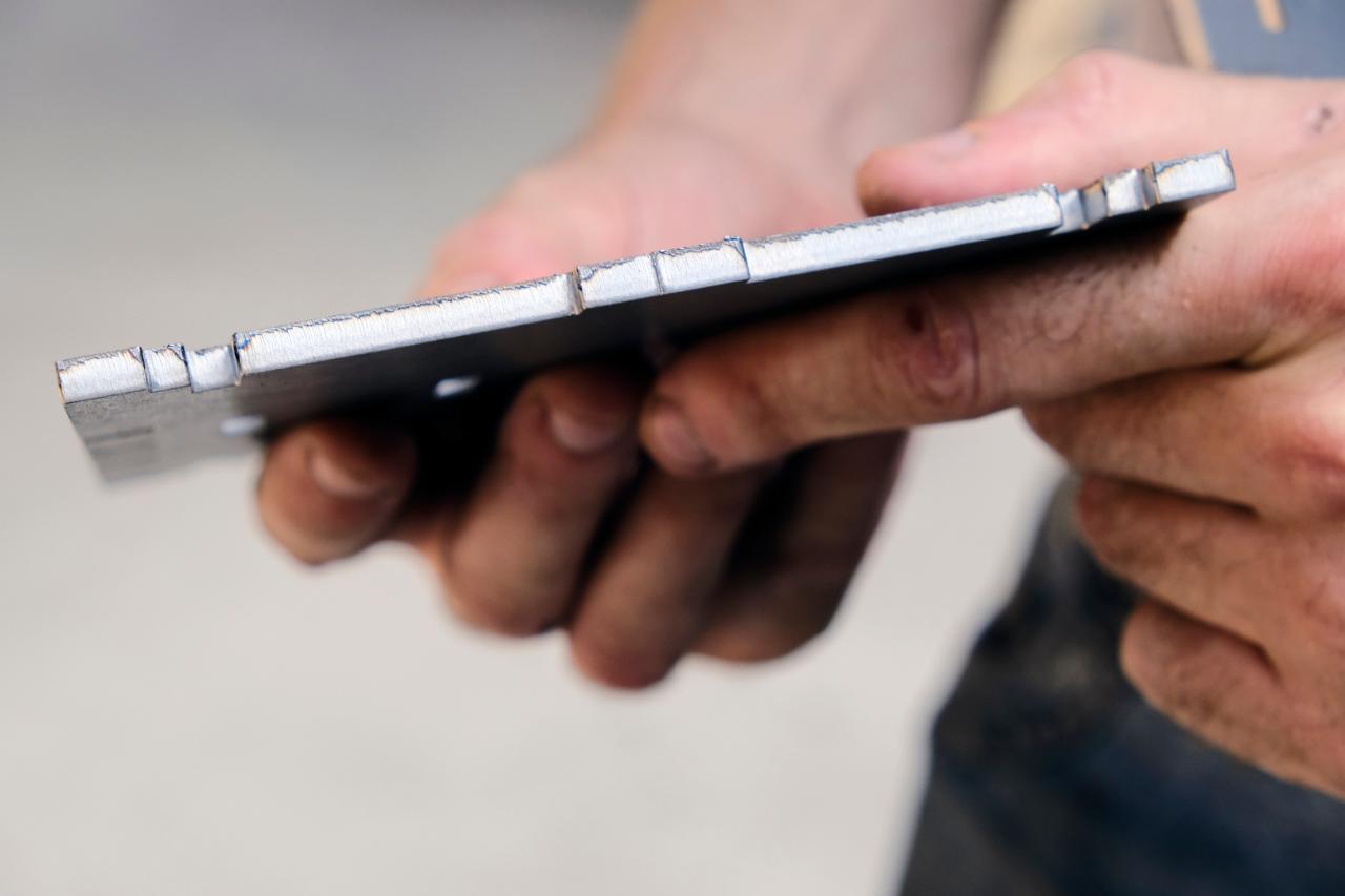
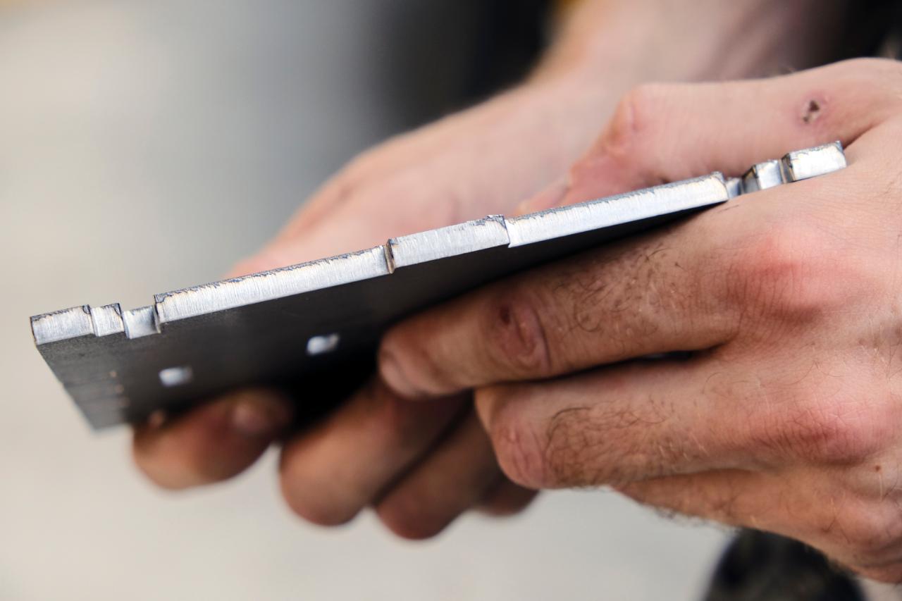
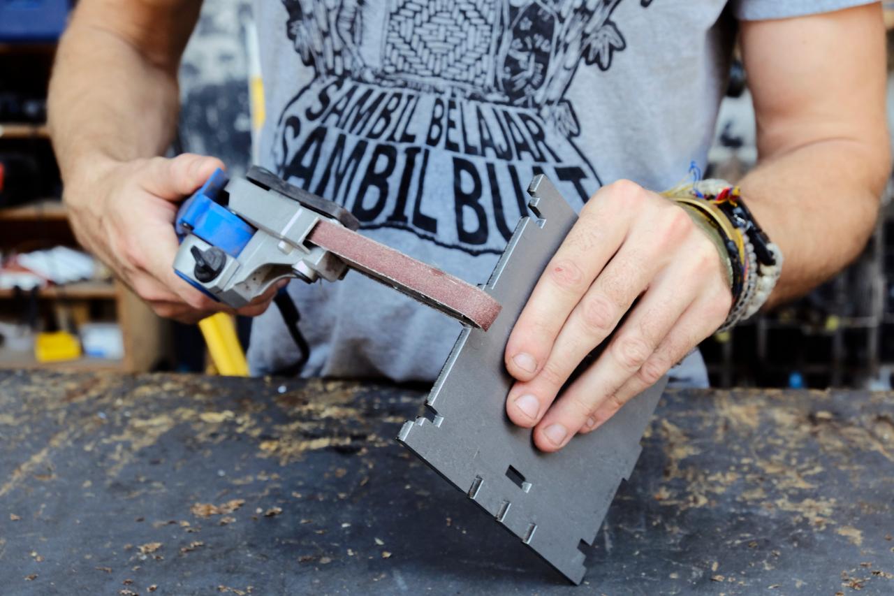
Step 3 - Preparation of parts
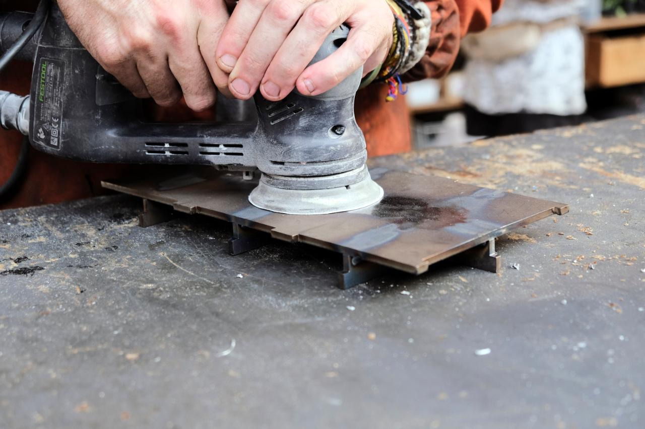
Before assembling your mould for welding, all rough edges created by the laser cutting will need to be removed so the mould can be assembled tightly. To do this we used a handheld sander however this can easily be done with a Dremel or by hand with a file. Take extra care not to damage the sharp corners of the metal.
Step 4 - Assembly
The mould comes in 3 key parts. The female top section of the mould requires no welding and is made of interlocking parts that are bolted together. The male lower section is completely welded. Each piece is also named very specifically to help you order and assemble. These names will also be engraved onto the mould to help you assemble.
For example AB5x2.
“A” - First letter defines what part group it belongs to.
“B” - Second letter defines which part it is in that group.
“5” - First number defines the thickness of the metal in mm the part is made from.
“x2” - Specifies the number of pieces required per order to complete the mould.
For example AB5x2.
“A” - First letter defines what part group it belongs to.
“B” - Second letter defines which part it is in that group.
“5” - First number defines the thickness of the metal in mm the part is made from.
“x2” - Specifies the number of pieces required per order to complete the mould.
Step 5 - Assembly of the top section (Part A)
Each corner requires 1 bolt and 3 nuts. The bolt should be 45-50 mm long, the nuts are 10mm. Place 6 bolts through the top plate (AD5) and add an additional two nuts to each. This should be followed by the interlocking parts (AB5 & AC5) followed by the bottom plate (AA5). The ideal distance of the two plates (AA5 & AD5) is 20 mm.
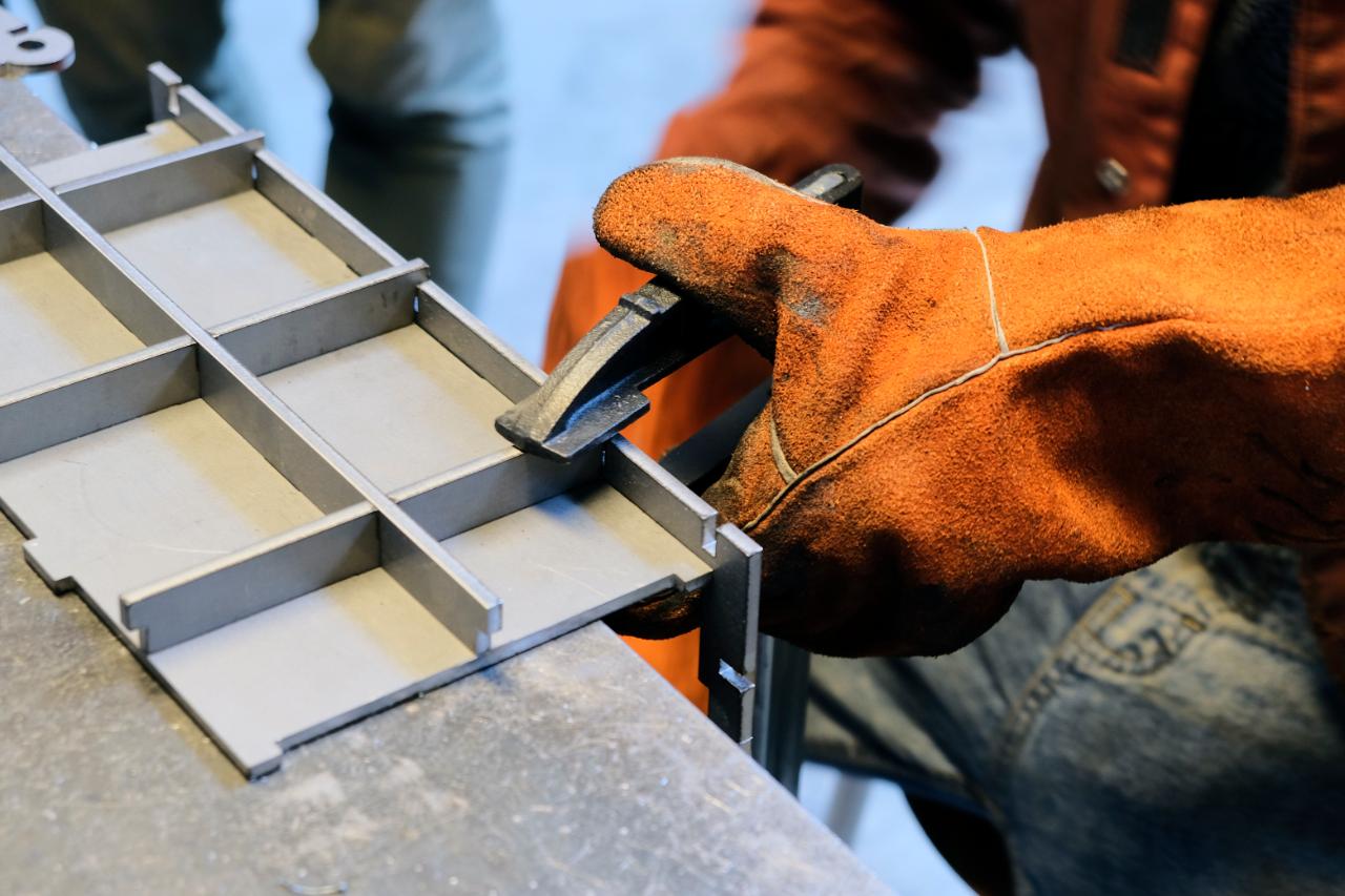
Step 6 - Put sides together (Part B)
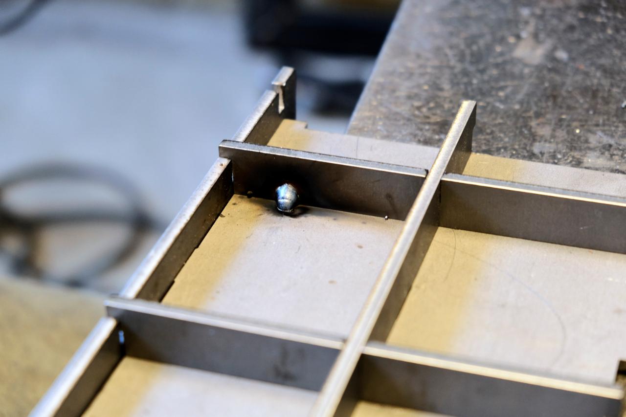
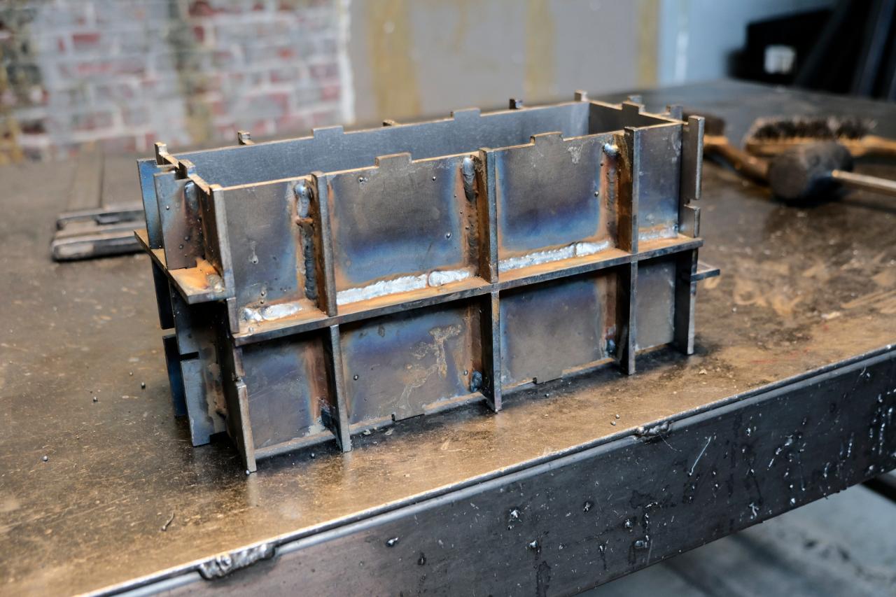
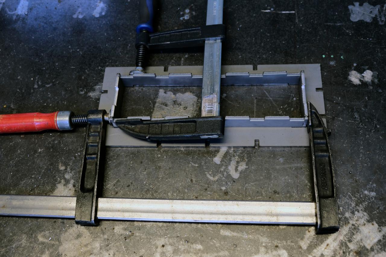
It is easiest to weld the supporting ribs (BB5, BC5, BE5 & BF5) to the 4 side plates before assembling the sides. To do this place the main plate on the welding table and clamp the ribs individually as you weld. Ensuring the main plate remains flat and does not warp. You will need to use (BG5) to ensure even spacing at the top and bottom.
Repeat these steps for the other 3 sides.
Repeat these steps for the other 3 sides.
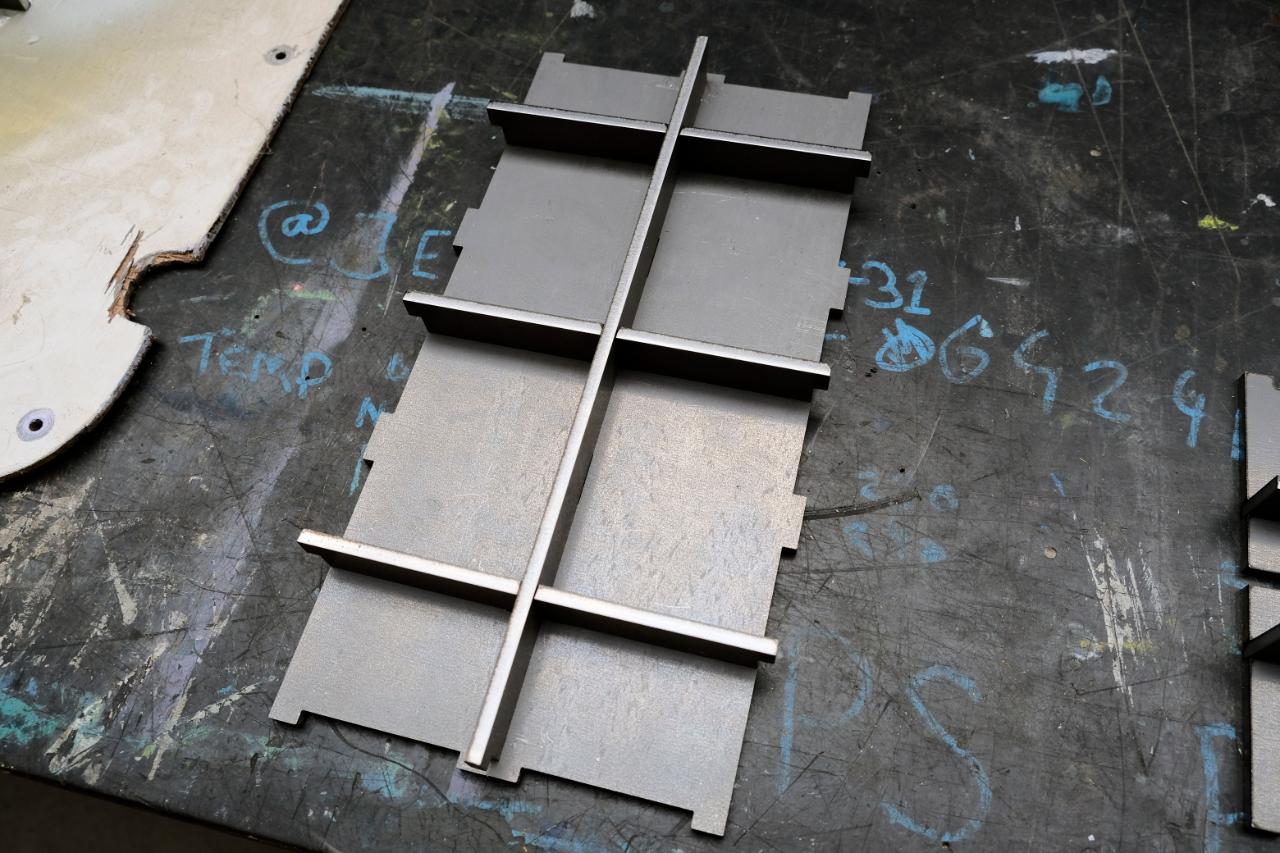
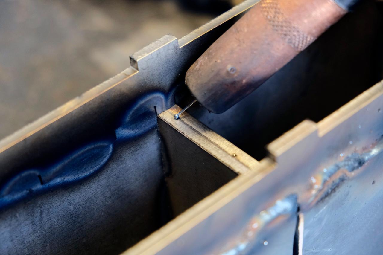
Step 7 - Internal welding
Once all of the ribs have been tacked, turn the plates over and weld (while clamped) the groves.


Step 8 - Smoothing the inside
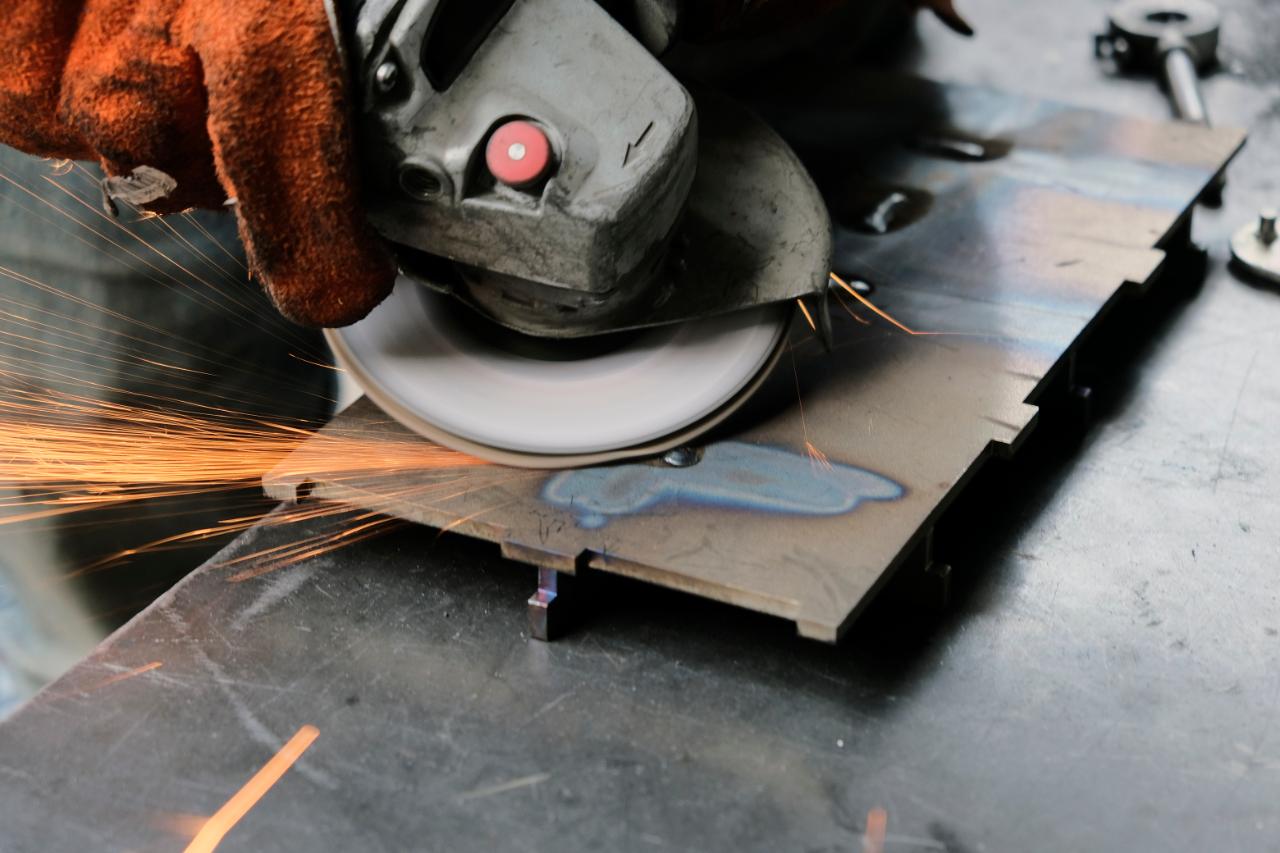
Once cooled, grind away the welds ensuring the surface on the inside is completely smooth. Take care to not over grind the weld. Then sand the surface removing any finer imperfections.
Step 9 - Putting the sides together
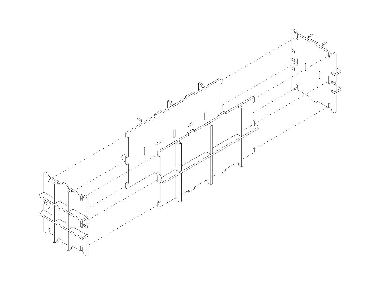
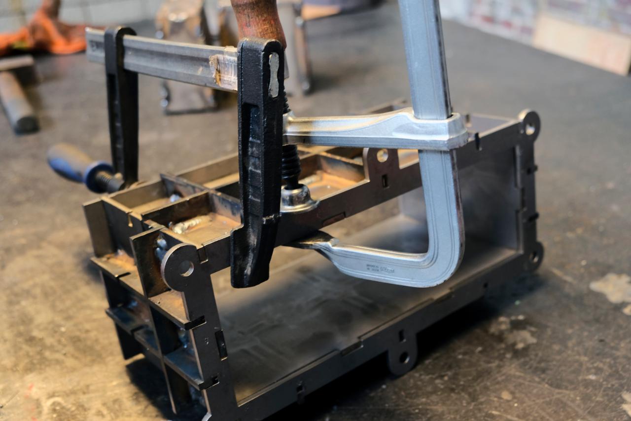
Once all 4 sides have been sanded on the inside, place them together as seen in the diagram and weld them together. A clamp may be useful in this process.
Step 10 - Adding the bottom and top frame
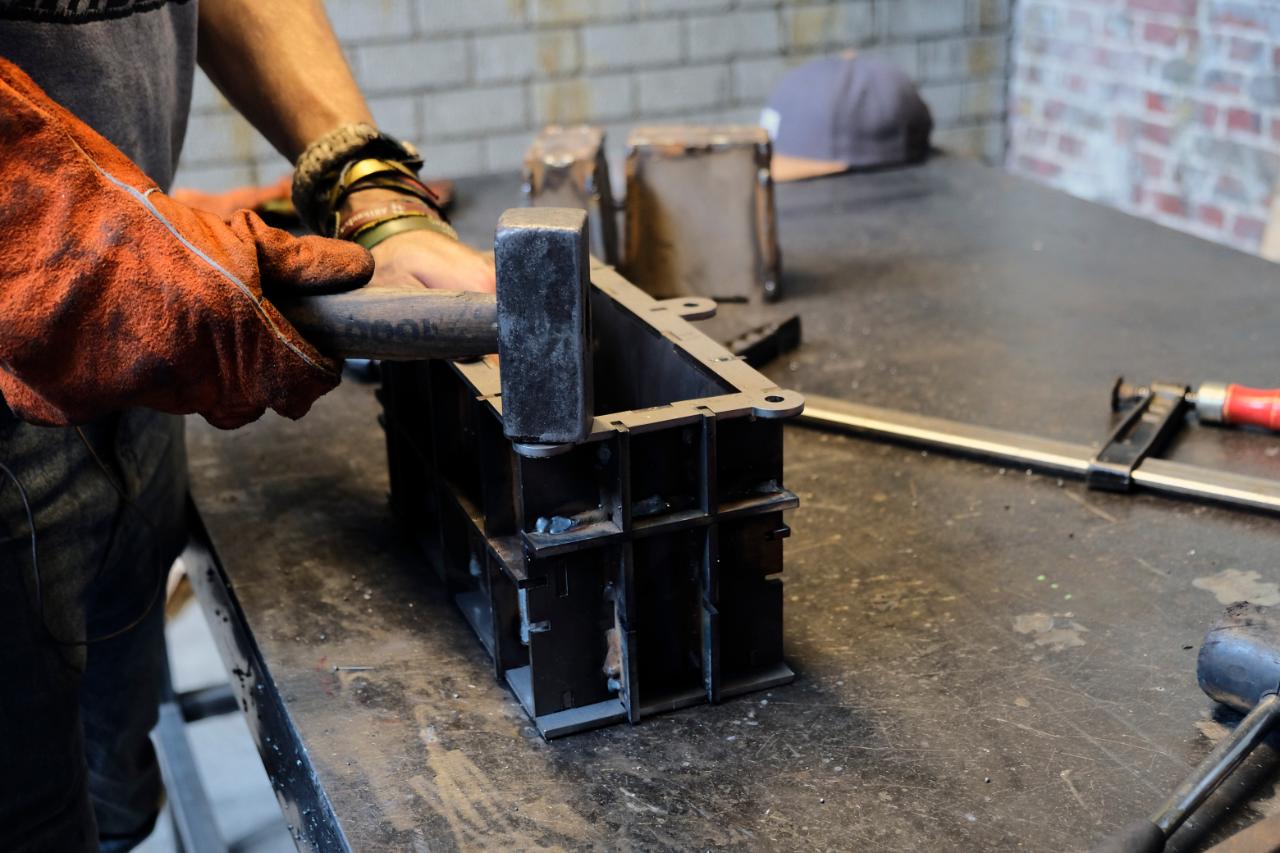
Once all 4 sides have been welded. Place part number (BG5) on the bottom and part (BI5) on the top. This may need a gentle hammering to fit, but must not be forced otherwise it may bend.
Once in place clamp together. Ensuring the inside surface is smooth and weld any external surface.
Once in place clamp together. Ensuring the inside surface is smooth and weld any external surface.
Step 11 - Prepare the male mould (Part C)
The male part of the mould is the final section but is probably the most complicated to assemble. Take these stages slow.
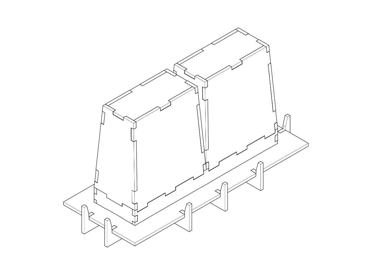
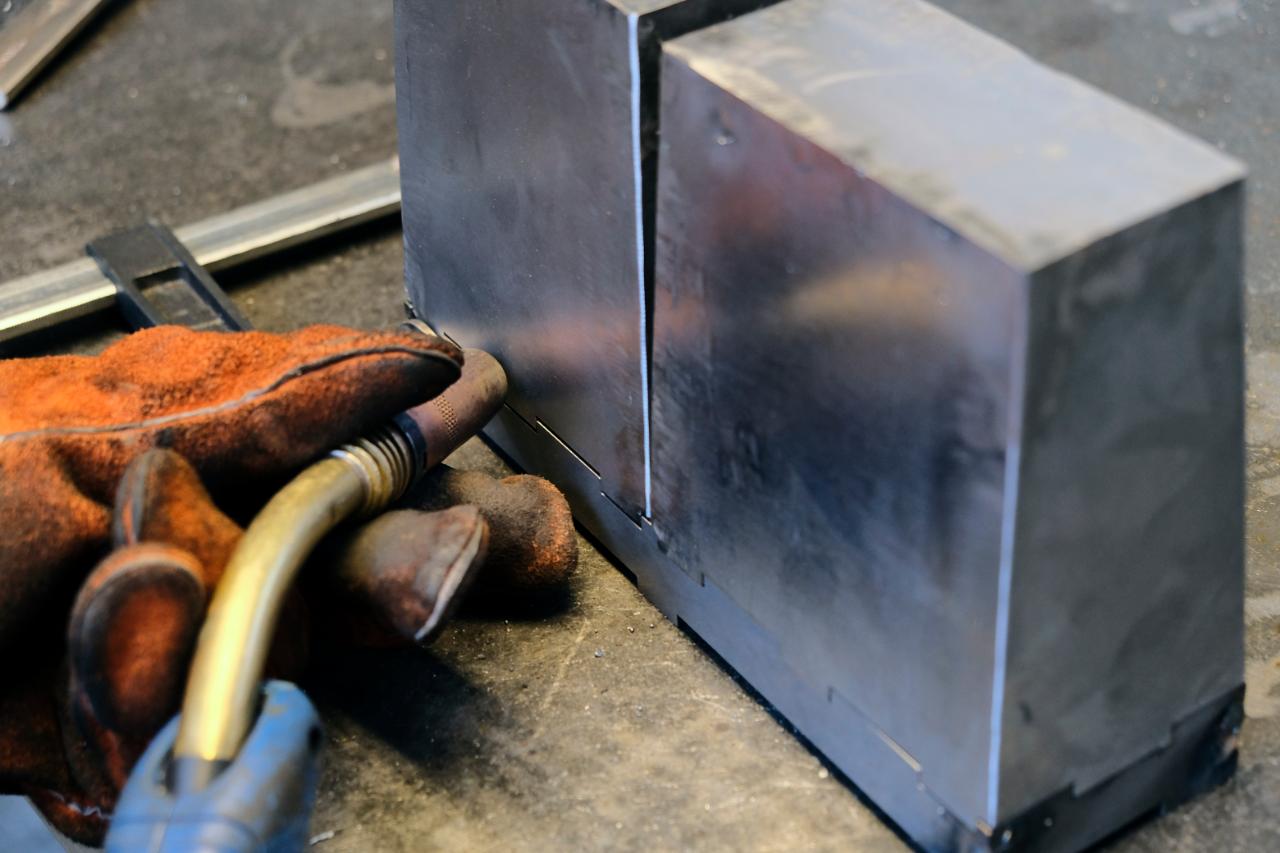
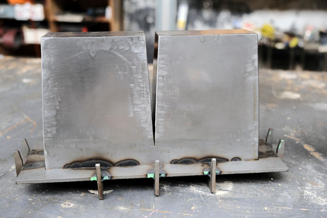
Step 12 - Weld each hump individually
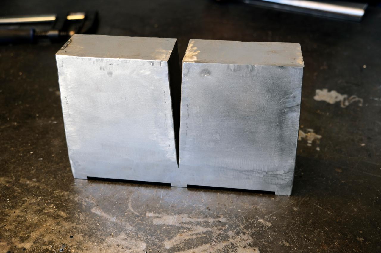
The main section comes in many parts that we are going to tackle one at a time. The first is the humps. There are two and they are identical. Clamp them together and weld them along the seams. Preserving the corners.
Like in step 8, use an angle grinder and sander to achieve round and smooth corners.
Like in step 8, use an angle grinder and sander to achieve round and smooth corners.

Step 13 - Weld the base
Using part CA5 align parts CE5 and CF5, clamp and weld. Avoid welding CA5 at this point.
You should be left with a perfect frame to attach the two humps too.
You should be left with a perfect frame to attach the two humps too.
Step 14 - Welding the humps to the base
Now place the humps on top of the base frame and clamp them tight together.
First weld around the outside, then turn the mould over and weld the point where the two humps meet to avoid plastic leaking in the future.
Finish by grinding and sanding the welds again for a smooth surface and round edges.
First weld around the outside, then turn the mould over and weld the point where the two humps meet to avoid plastic leaking in the future.
Finish by grinding and sanding the welds again for a smooth surface and round edges.
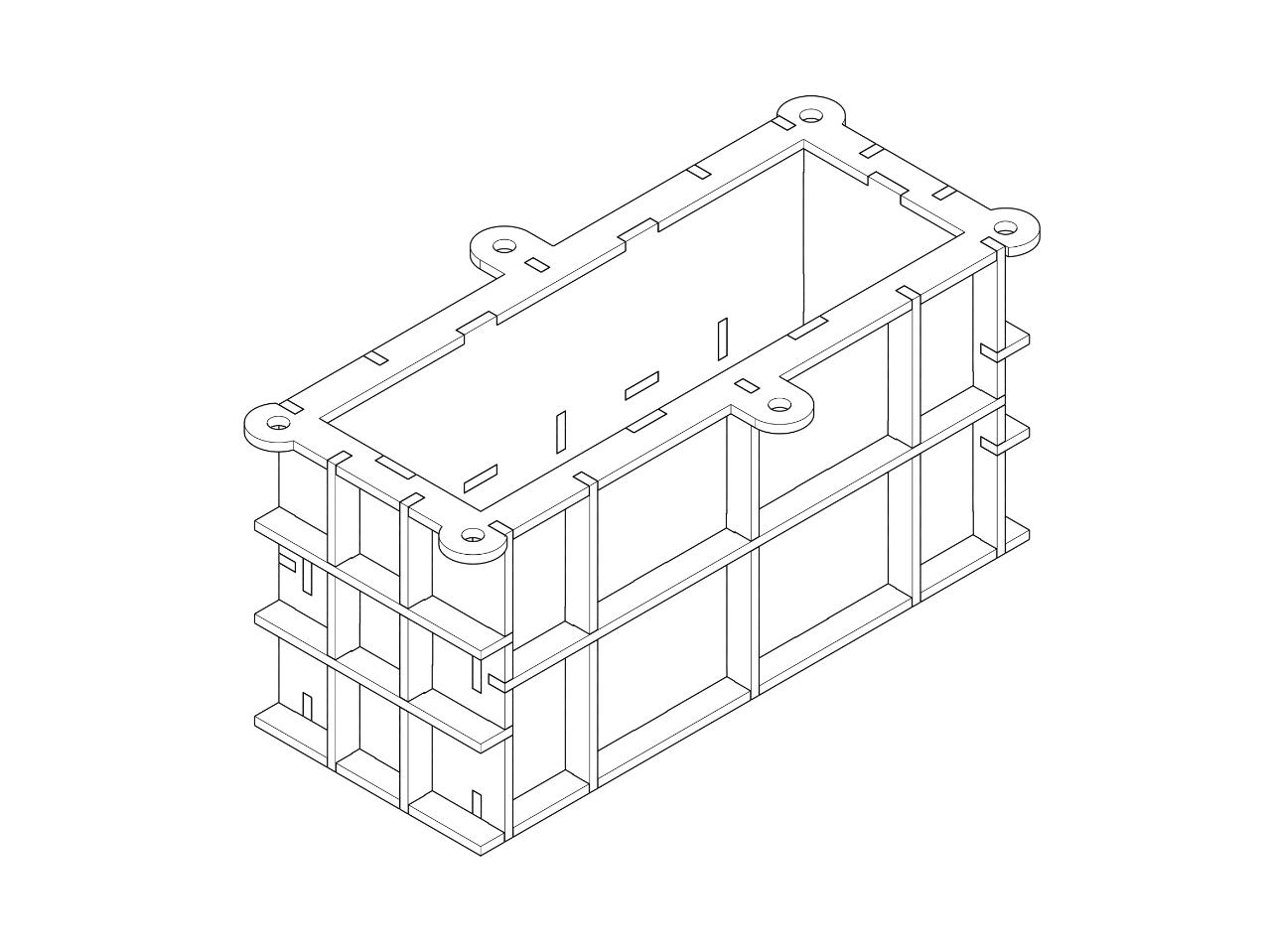
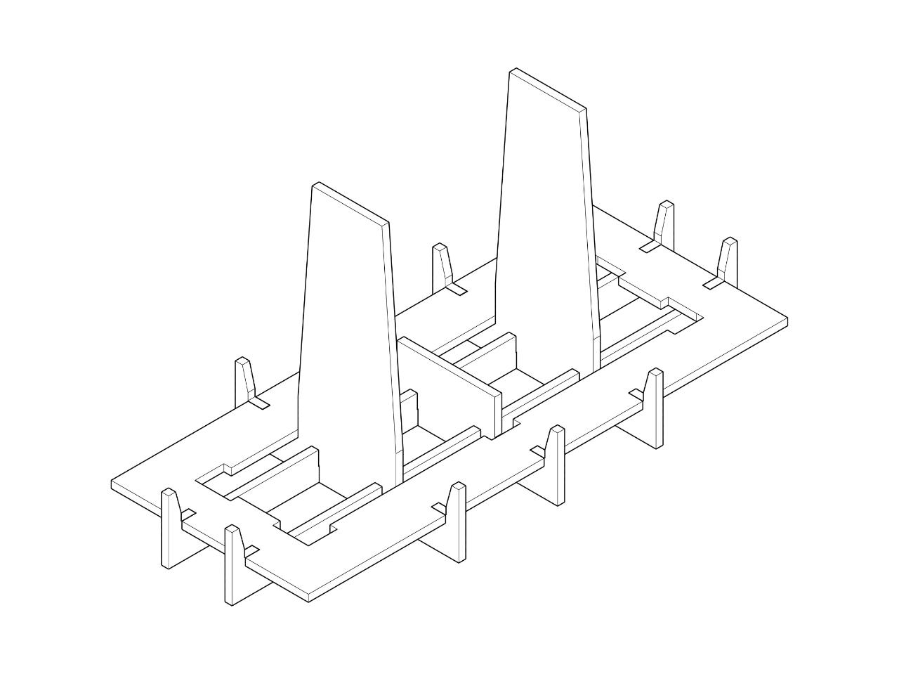
Step 15 - Adding the support structure
Take part CA5 and clamp to the base, Tack welding on the inside only baring in mind that parts CB5, CC5 and CCD will be placed inside. Once all parts are placed inside weld all accessible ribs in full. Clamping like previous steps.

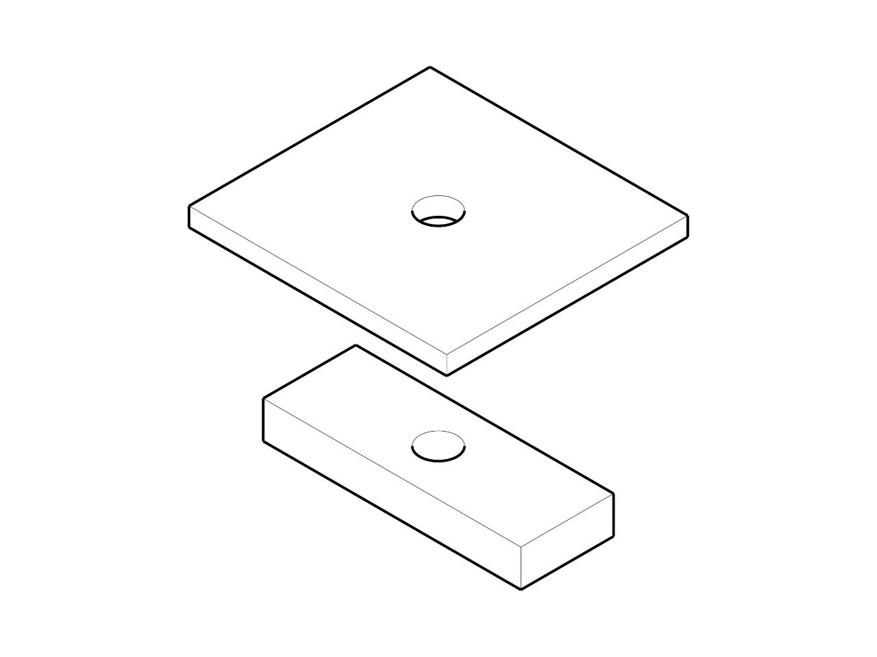
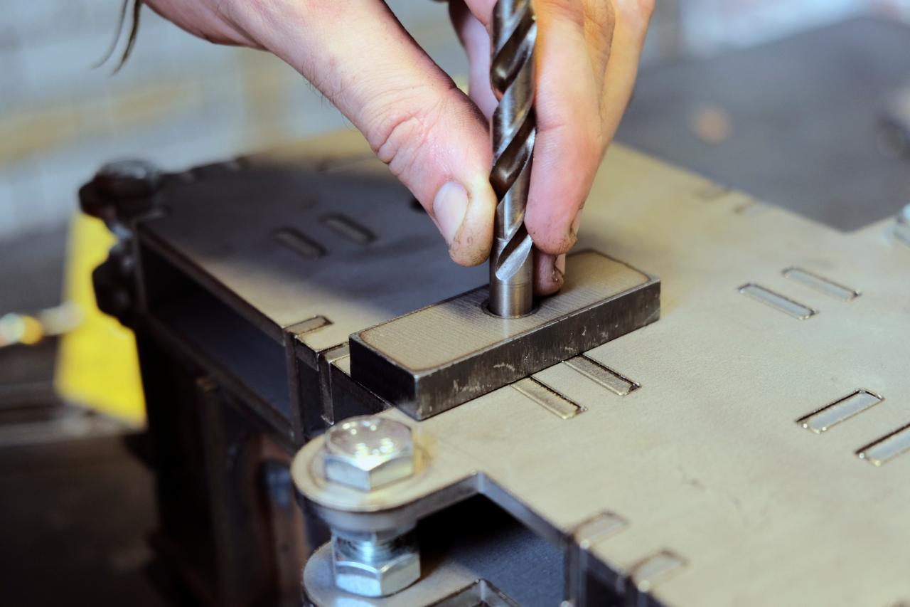
Step 16 - Add the quick release nozzle
Take part DA10 and place it onto the surface of AD5 in the marked out space. Use an 8mm drill bit to ensure perfect alignment of the holes and weld only on the shortest of the two sides. Then place part DB5 ensuring it fits with your extrusion adapter. (See Extrusion Adapter How To). Again welding only the top sections.
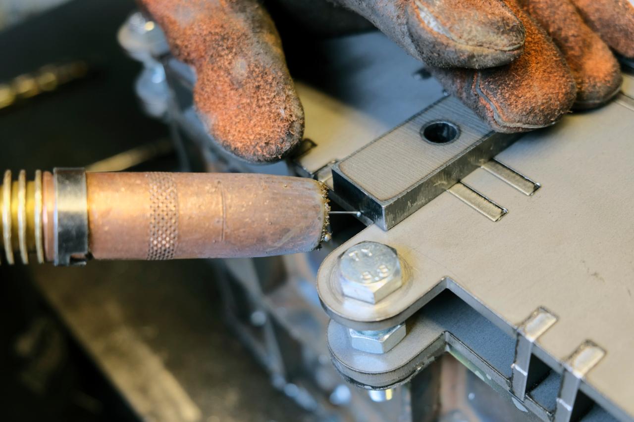
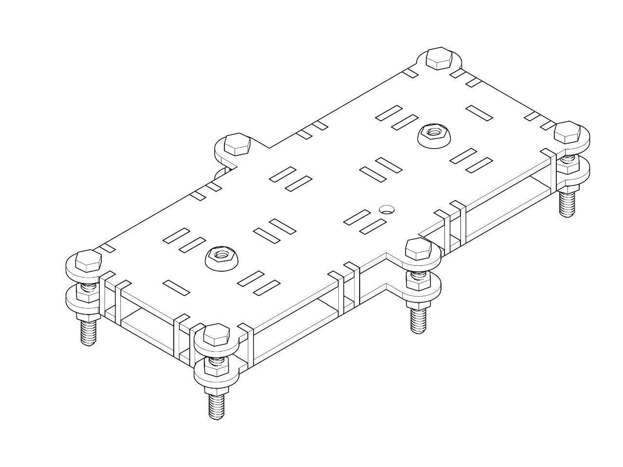
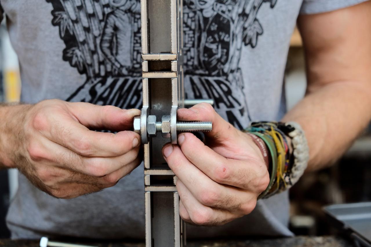
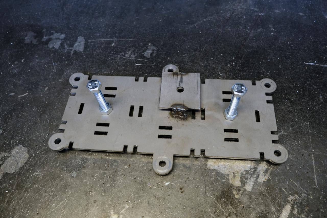
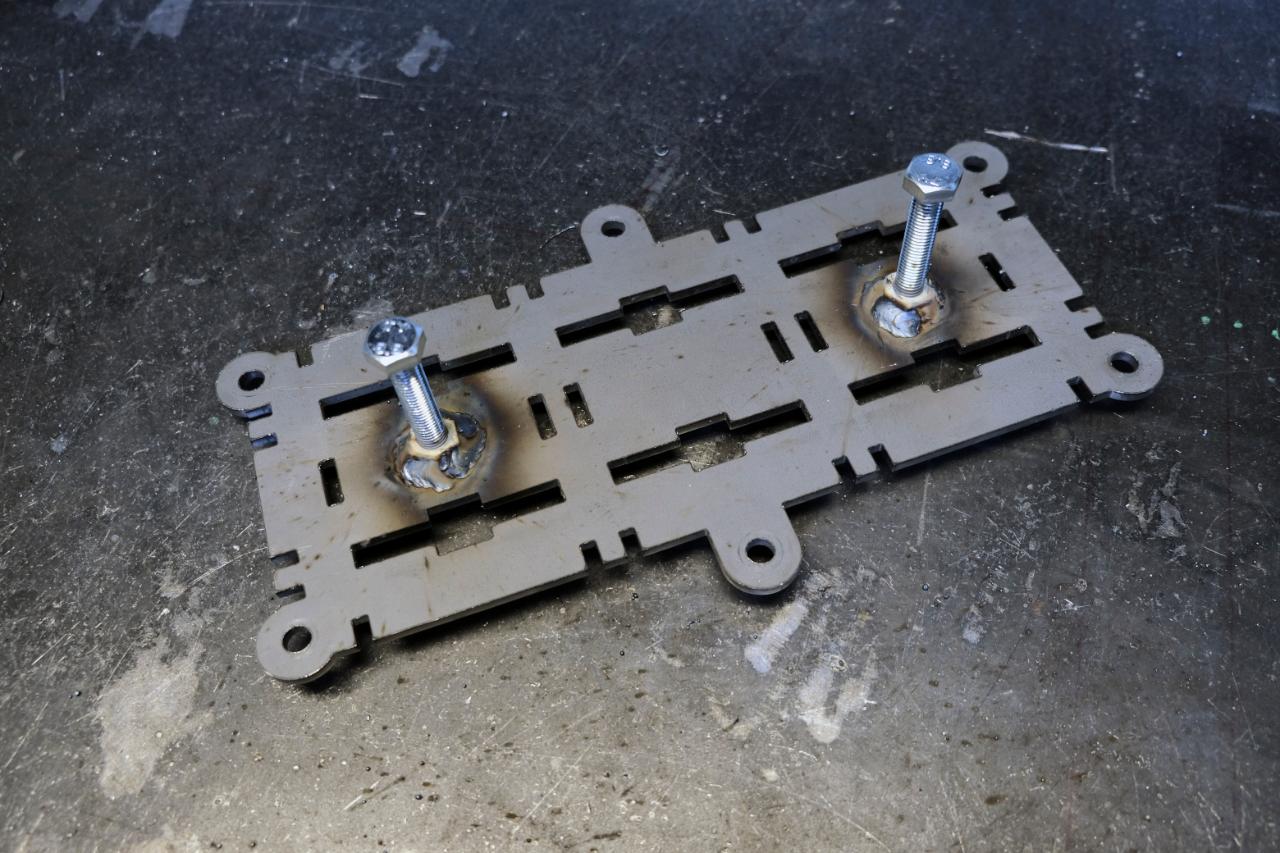
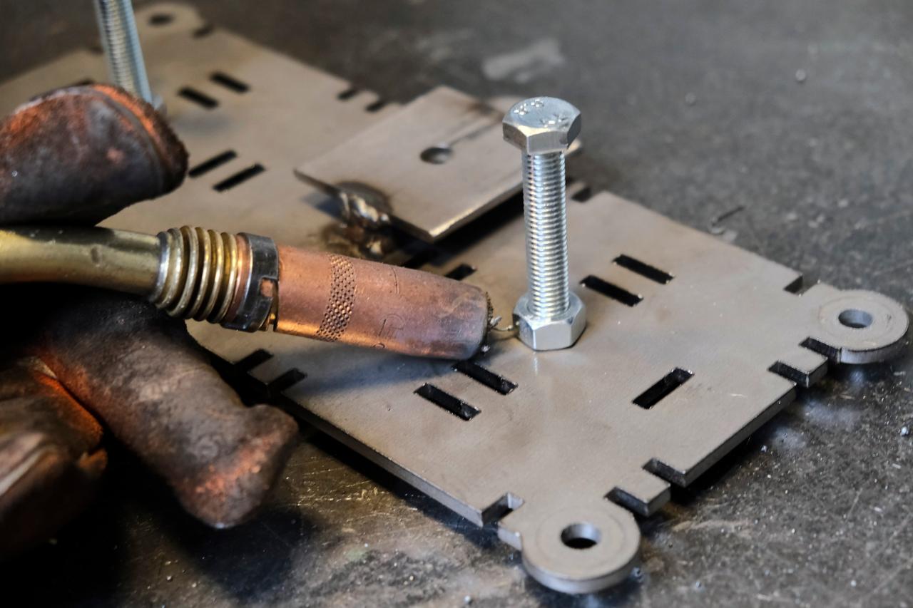
Step 17 - Adding bolt release mechanism
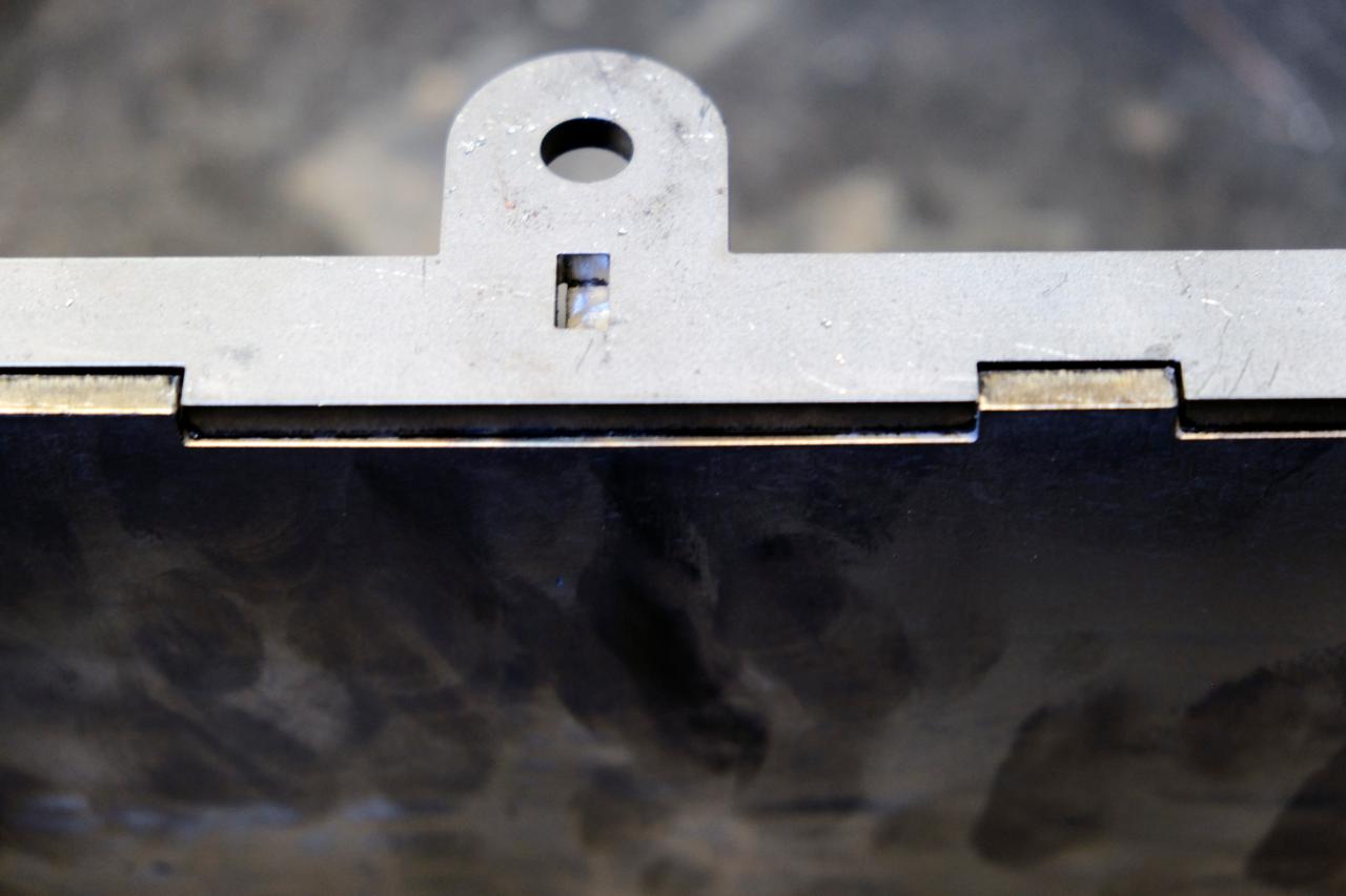
To ensure we can always take the mould apart we need to install a set of bolts that prevent the mould from being stuck together. To do this, we disassemble the top section of the mould (Part A). Taking part AD5x1, thread a bolt through the bottom of the two 12mm holes and tighten the nut until it is placed firmly on the surface of the part. Then weld the nut that is on the top surface of the mould, ensuring no weld touches the nut.
Repeat with this process with part AA5.
Repeat with this process with part AA5.
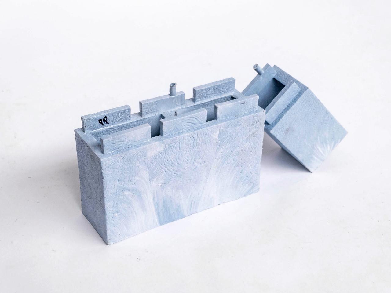
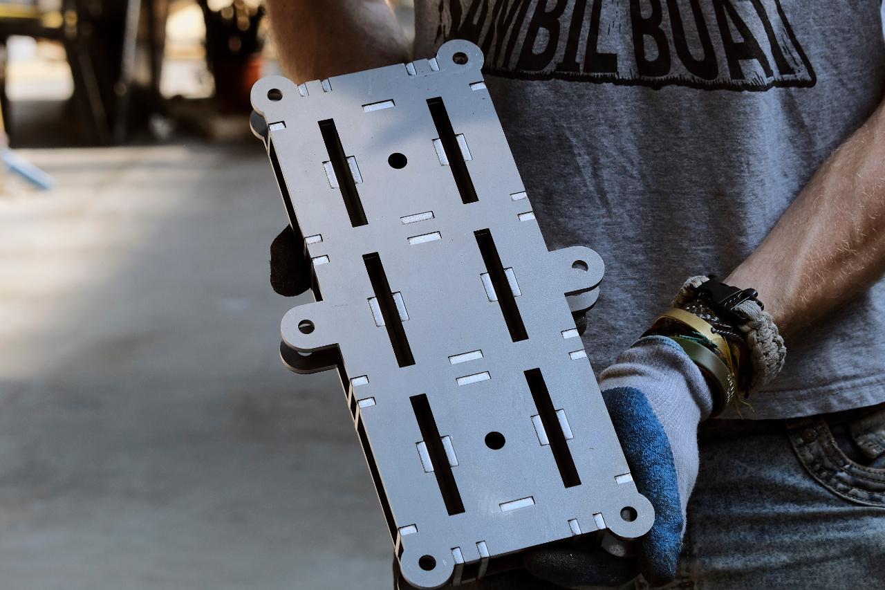
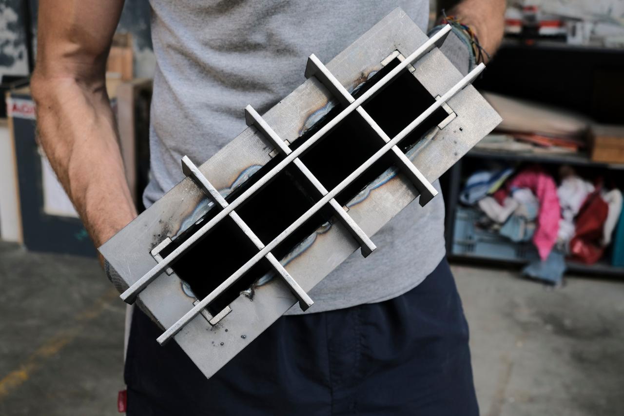
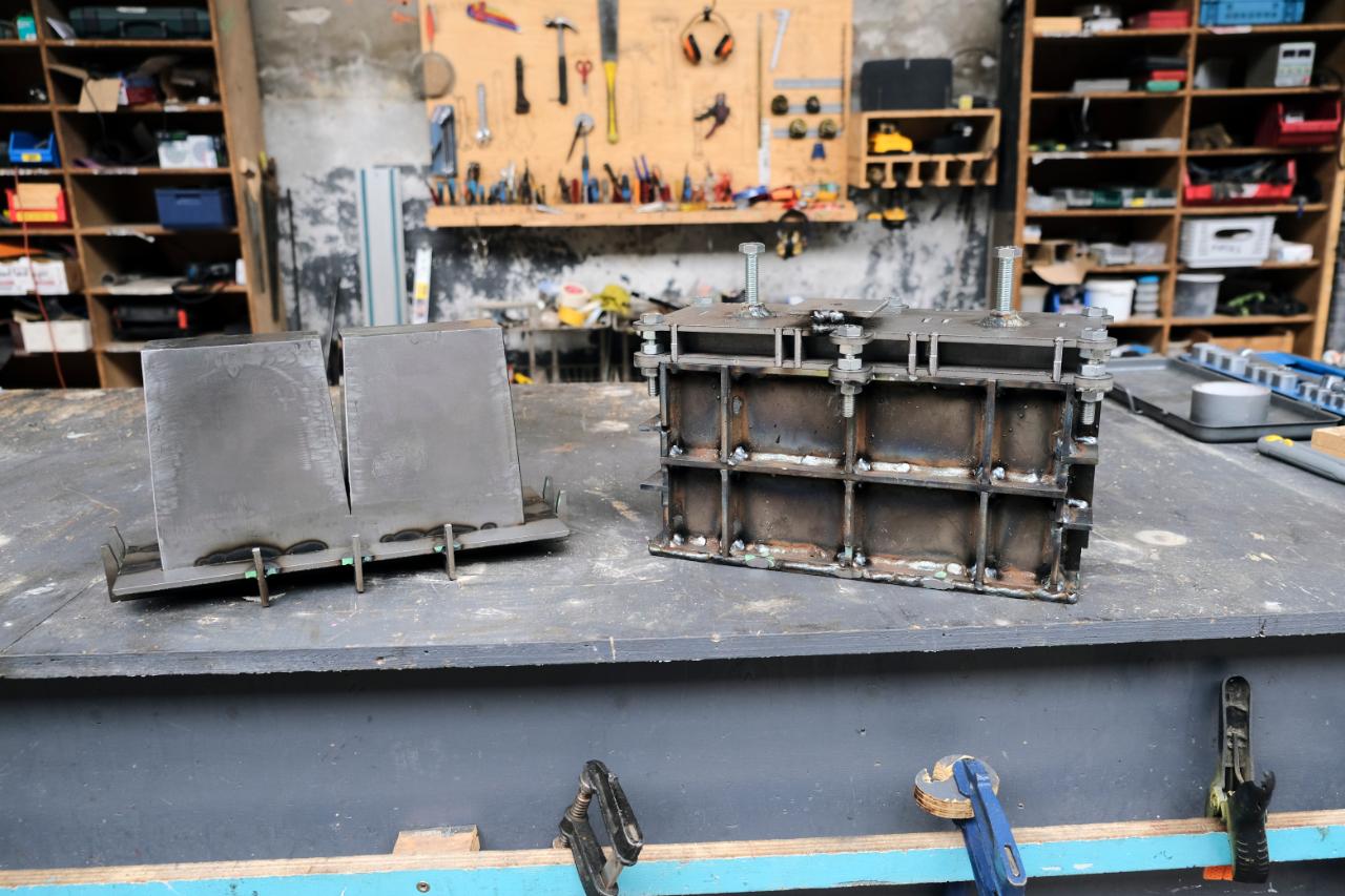
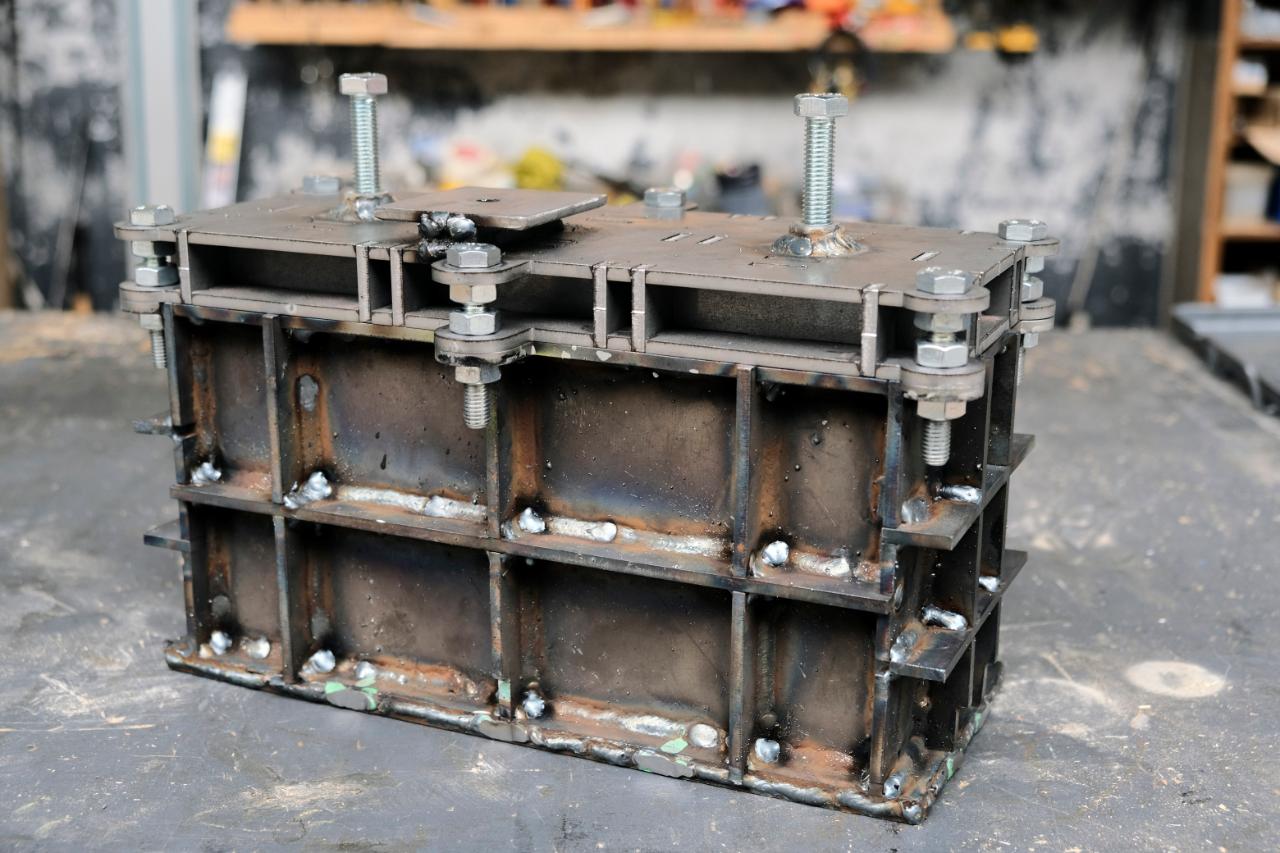
Step 18 - Fully assemble
Fully assemble all parts, connecting A to B using bolts. and you should be left with something like this.
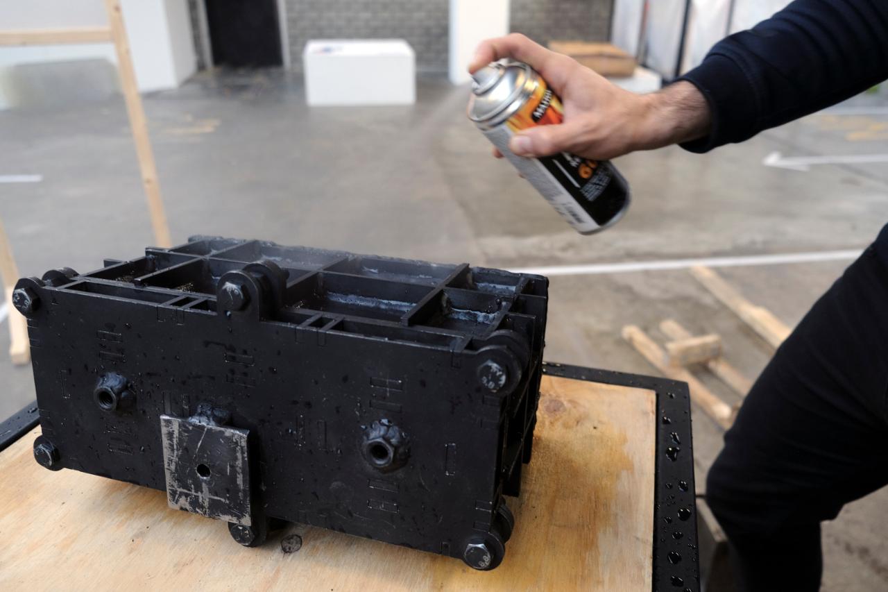
Step 19 - Paint
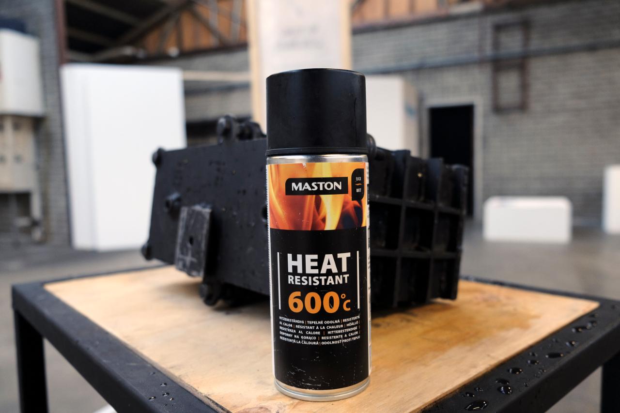
The mould is almost ready. Depending on if you purchased a Stainless Steel mould or Mild steel, you may want to combat rust with a nice coat of paint.
You will need something that can handle high temperatures above 300c, we use paint for fireplaces or engine parts. Spraying only the external surfaces of the mould. To protect the inside of the mould we use light rubbing of oil after every use.
You will need something that can handle high temperatures above 300c, we use paint for fireplaces or engine parts. Spraying only the external surfaces of the mould. To protect the inside of the mould we use light rubbing of oil after every use.

Step 20 - Ready to make bricks!?
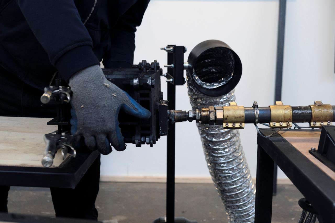
Well done, now you’re ready to extrude!
Find advice for the extruding process in the How-to “Extrude into closed moulds”:
👉 https://community.preciousplastic.com/how-to/extrude-into-a-closed-mould
And learn how to "Build brick structures":
👉 https://community.preciousplastic.com/how-to/build-brick-structures
Find advice for the extruding process in the How-to “Extrude into closed moulds”:
👉 https://community.preciousplastic.com/how-to/extrude-into-a-closed-mould
And learn how to "Build brick structures":
👉 https://community.preciousplastic.com/how-to/build-brick-structures
—
—
—
Comments