XL Long bed 3D-printer conversion
-1810a0c7176.jpg)
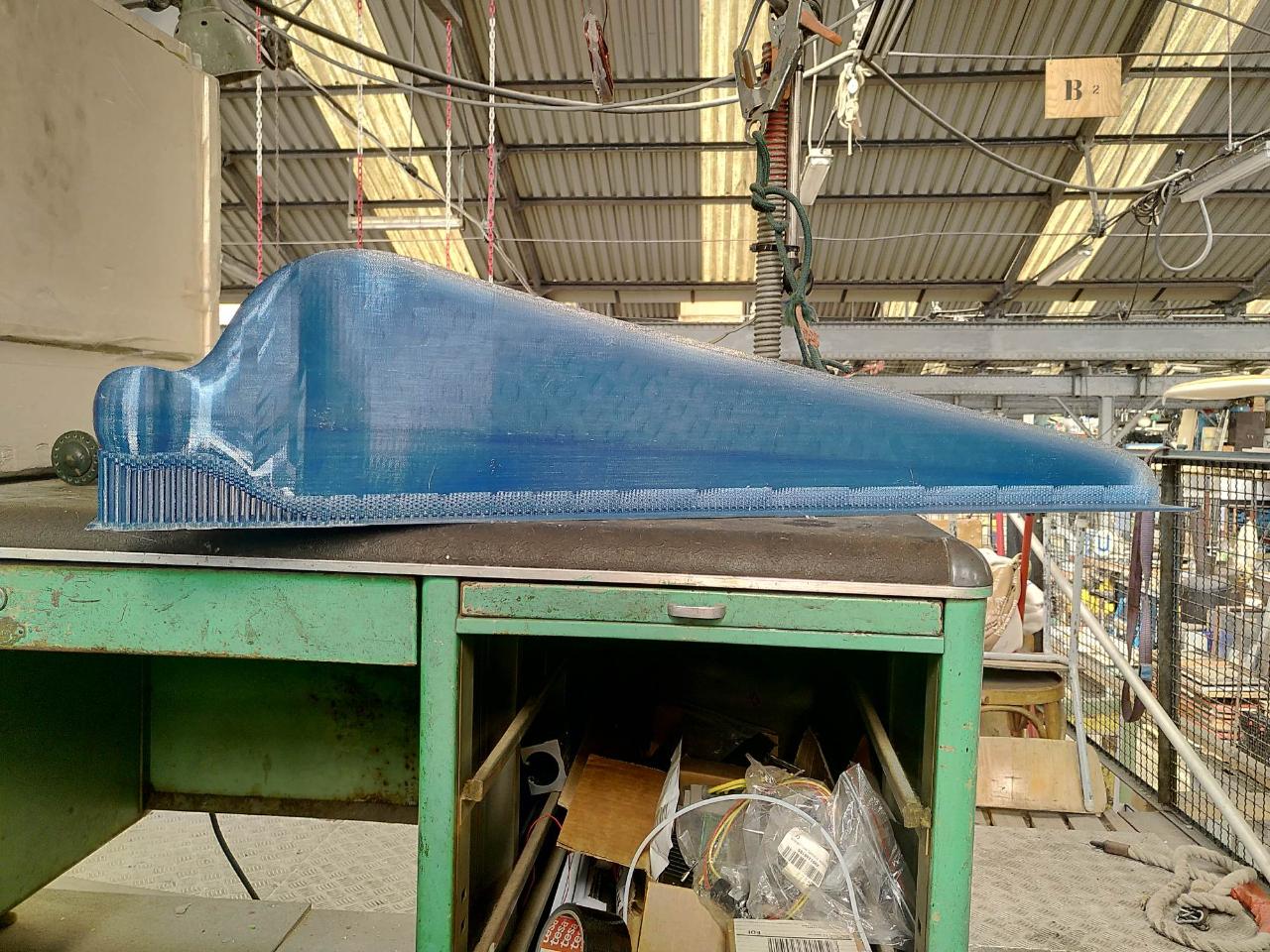
This how-to will show how to fit a longer bed on any flashable 3D-printer. We use the long bed ourselves to print windturbines (more about that on the Precious Plastic Research module: <a href="https://community.preciousplastic.com/research/make-a-windturbine-from-recycled-plastics)">https://community.preciousplastic.com/research/make-a-windturbine-from-recycled-plastics)</a>
—
Attachments
Resources
Step 1 - Gather all required parts
Necessary for this build:
Basics:
- a basic 3D-printer that allows modifying the firmware (we use an Anycubic I3 Mega S)
- a rigid table of 2m * 80cm or bigger to put everything on
Movement system (Y-axis):
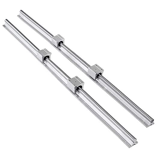
- 2 * SBR25 1500mm rails
- 4 * SBR25UU bearings + bearing holders
- 2,5m glassfiber belt for 3D-printers (often called GT2 belt). 2mm pitch.
The heated bed:
- 5 aluminum profiles of 40x15mm
- NiCr heating wire of 60 ohm 3A, 5 or 10m length
- glassfiber sleeving to insulate the heating wire (resistant to 150 degrees Celsius or more).
- 16 * 8mm threaded rods of 5cm length + 32 nuts for both sides
- (recommended) glassfiber cloth (50 x 50cm)
- basic tools: a drill, screws, bolts and nuts
Basics:
- a basic 3D-printer that allows modifying the firmware (we use an Anycubic I3 Mega S)
- a rigid table of 2m * 80cm or bigger to put everything on
Movement system (Y-axis):
- 2 * SBR25 1500mm rails
- 4 * SBR25UU bearings + bearing holders
- 2,5m glassfiber belt for 3D-printers (often called GT2 belt). 2mm pitch.
The heated bed:
- 5 aluminum profiles of 40x15mm
- NiCr heating wire of 60 ohm 3A, 5 or 10m length
- glassfiber sleeving to insulate the heating wire (resistant to 150 degrees Celsius or more).
- 16 * 8mm threaded rods of 5cm length + 32 nuts for both sides
- (recommended) glassfiber cloth (50 x 50cm)
- basic tools: a drill, screws, bolts and nuts
Step 2 - Assemble the bed
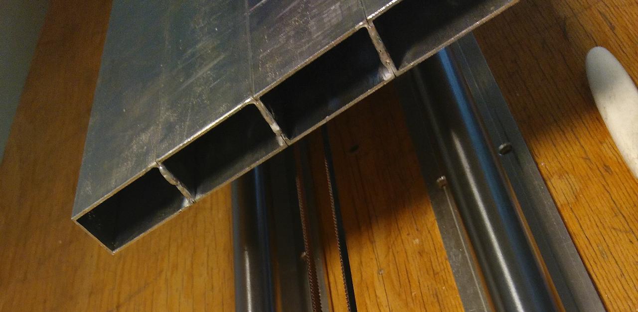
1. Weld the aluminium profiles so they are connected and make a platform of 1m * 20cm. Preferabbly this happens on the ends only so they are not skewed or distorted by the welding process.
2. Drill holes for the bearing holders. They should be 1m apart.
3. Install the bearings approximately 5cm from the bed
4. Put the glassfiber sleeve over the NiCr heating wire and pull it through the hollow spaces of the aluminum bed
5. (Recommended) Put some glassfiber cloth at the end of each alumium profile so the air stays inside
Step 3 - Make the base: rails on a sturdy table!
Make sure the table is flat and can't bend or move, because this will have a great impact on the printability.
Probably the rails will become dusty because of the installation process, so make sure to clean them and apply some TPFE-oil before moving to the next step.
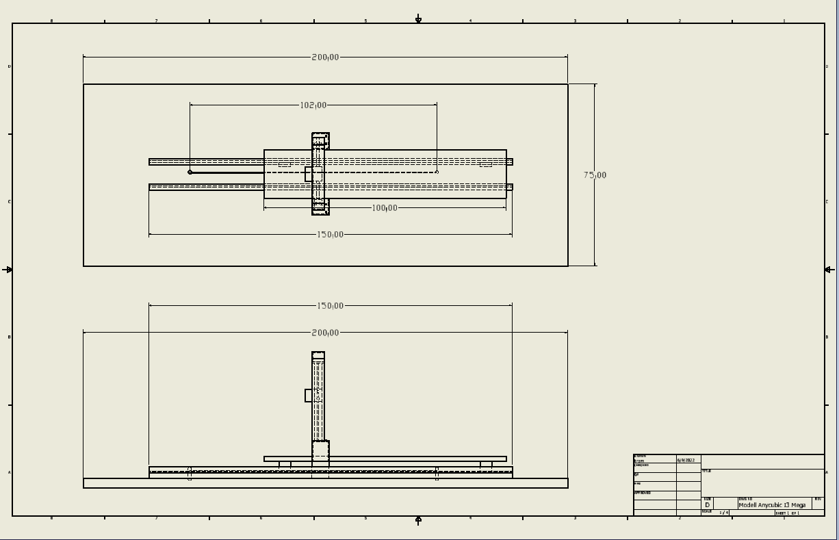
Before proceeding to the next step, check out the technical drawing on how the rest of the parts should be set-up.
Probably the rails will become dusty because of the installation process, so make sure to clean them and apply some TPFE-oil before moving to the next step.
Before proceeding to the next step, check out the technical drawing on how the rest of the parts should be set-up.

Step 4 - Assembling of the main parts
1. Drill holes for the mounting of the Y-axis. The screws that go into the stepper are very small so we made an adapter bracket with some left-over square aluminum bed for the pipe.
2. Mount both the stepper and pulley so they are approximately 1,25m apart
3. Get some sturdy L-hooks in steel, rvs or aluminium and drill some holes that fit the U-frame of your printer. By choosing these high enough we managed to get to a printable height of 26cm. 6 cm higher than normal!
4. Increase the length of the wire of the Y-stepper as much as necessary. We used some scrap 1,5mm² electricitycable because NEMA17 stepper can pull up to 2A current.
5. Mount the U-frame witl the L-hooks on the table and lower the endstops for the z-axis to benefit from the additional height
6. (Not in the video) Drill some holes to put the wires of the endstops and steppers through the table. In this way we managed to use all the original cables except for the Y-axis.
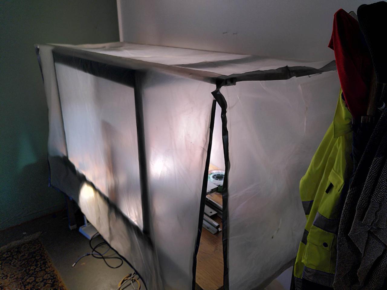
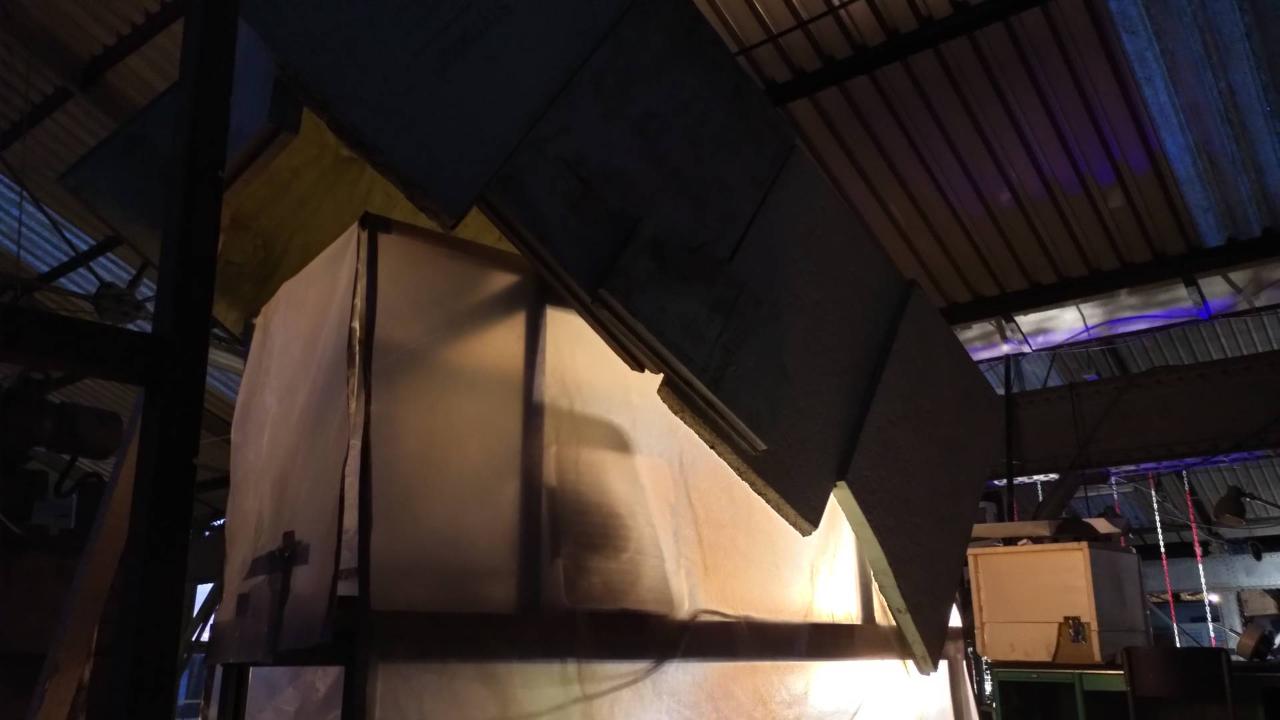
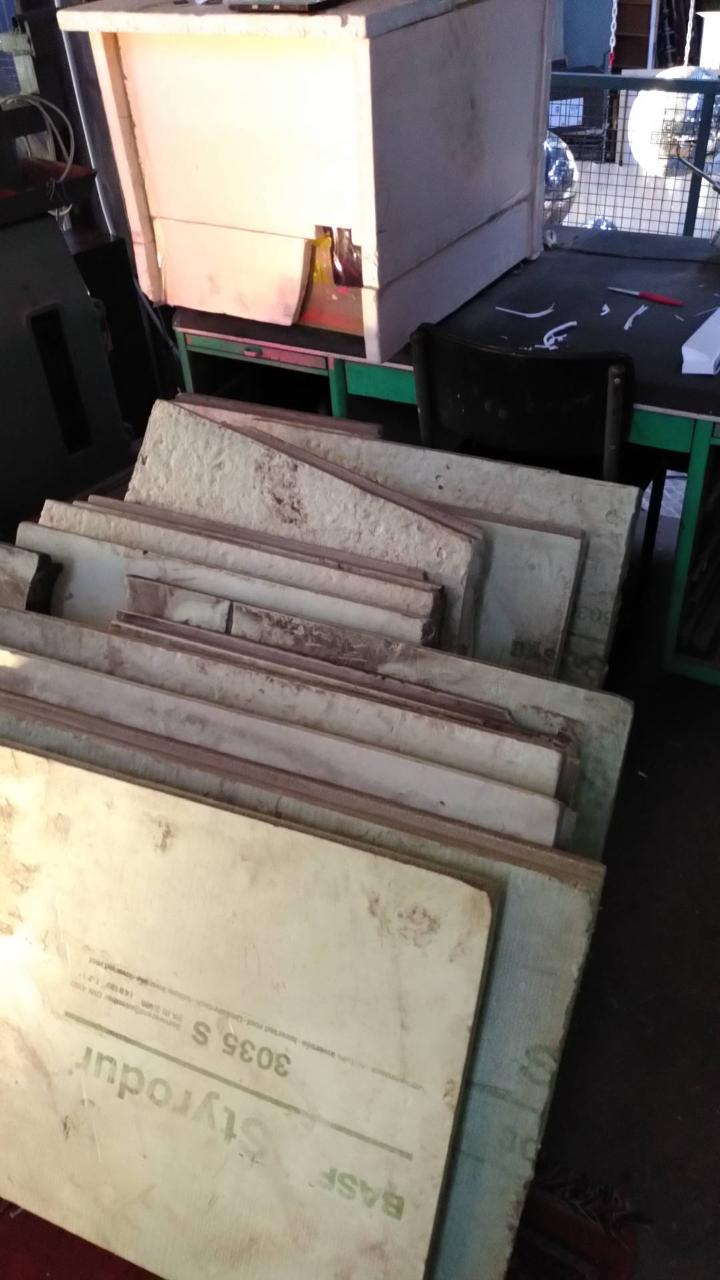
Step 5 - Make a heated chamber
Use your creativity to make a cover over the printspace. Plastic foil can already be enough to trap the warm air inside, depending on the room temperature. We also had good results with cardboard and left-over BASF Styropur, which is sturdy enough to not need a frame.
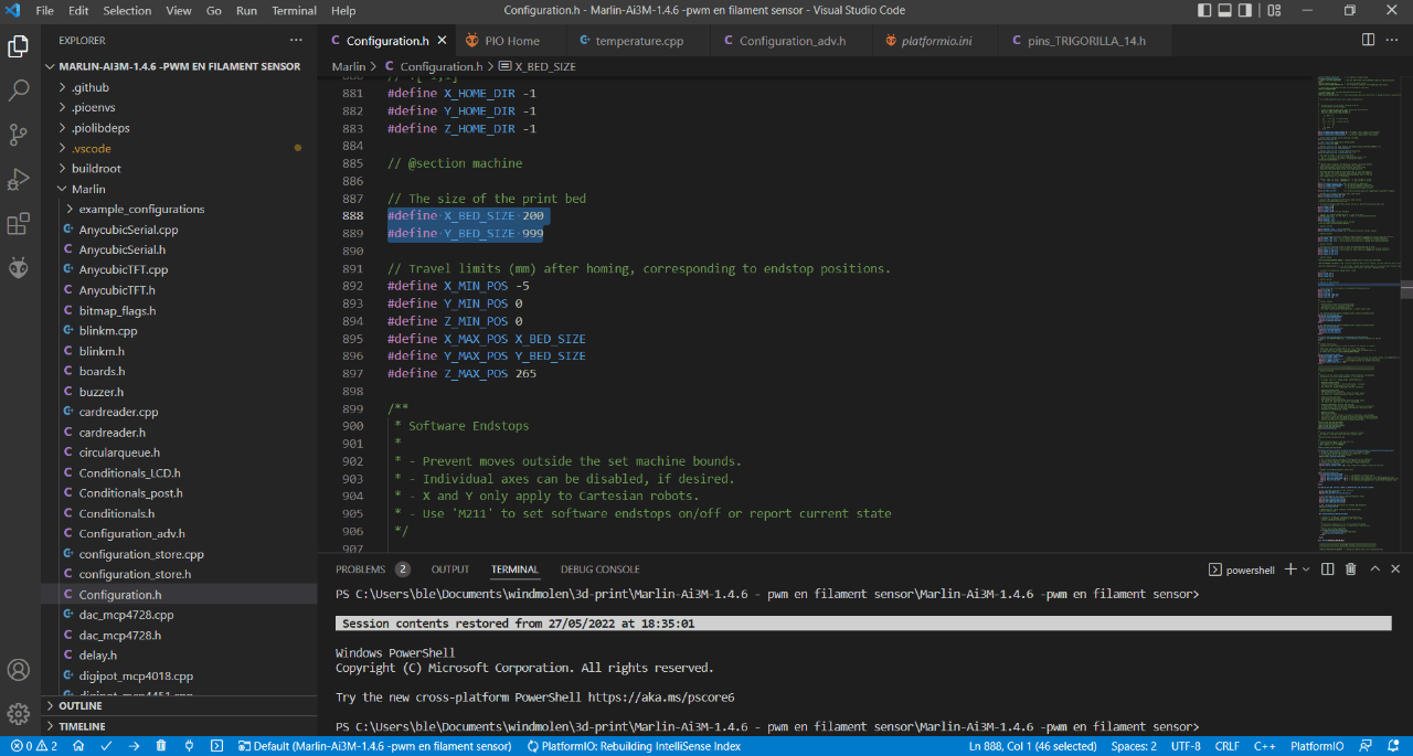
Step 6 - Download Marlin 1.4.6 and modify the bed size.
You can find an adapted version specially for the Anycubic I3 Mega S here: https://github.com/davidramiro/Marlin-Ai3M
Higher versions had a bugged manual bed leveling system, which we'll really need because it's easy to not have the bed exactly parallel to the table.
Install VSCode and open the code there. Change the following properties in configuration.h to let the printer know it has a bigger bed and higher build envelope:
a. Y_BED_SIZE: 999
b. MAX_Z_HEIGHT: 260
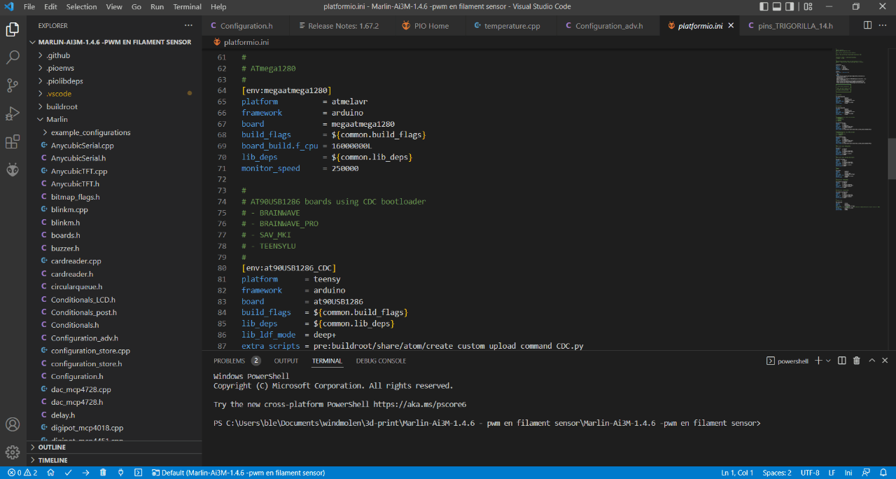
Step 7 - Flash the modified firmware
Connect your printer mainboard with USB. VScode will automatically connect to the right serial port.
Press the small arrow in the bottom left corner to start the uploading process.
Press the small arrow in the bottom left corner to start the uploading process.
Step 8 - Level the bed 'manually'
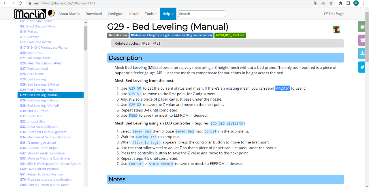
Ok, this is not the 'manually' as you used to know, turning the 4 knobs on the bottom of the printbed. Instead we will run the G29 S1 command, followed by G29 S2 until it finishes. The printer will calculate a grid of 5x5 points over the printbed and move to each position, where you'll be able to lower or heighten the nozzle on the z-axis.
(The number of points in the grid can easily be changed in the firmware)
More on the G29 command for Marlin: https://marlinfw.org/docs/gcode/G029-mbl.html
After you finished all 25 points, the printer will make a bleep sound and return the printhead to its 0,0 position. Be sure to save the grid with the M500-command. Also, before each print you should call M420 S1 to enable mesh-bed-leveling and fetch the modified z-coordinates. We can recommened to put this in the custom g-code section of your slicer to be sure to have it called before each print.
Step 9 - Test before you print big!
Printing big might take some time to get everything right. For example there might be some adhesion problems arising while printing. The bigger the object gets, the more power it has to warp and pull of off the bed.
We had good result printing rPET, PETG and PLA with Formfutur's Magigoo as an adhesive. Certainly PET(G) sticks very well and we use a first layer of PET(G) to print ABS.
We had good result printing rPET, PETG and PLA with Formfutur's Magigoo as an adhesive. Certainly PET(G) sticks very well and we use a first layer of PET(G) to print ABS.
Step 10 - Profit
This long bed conversion for example permits the printing of windturbine blades which allows yo uto build your own windturbines. Check our other tutorial to know more about it!
-181347fd79f.jpg)
—
—
—
Comments